Connector Pin-out
The electrical connection to the Certus OEM is through Molex and JST connectors to board mounted connectors.
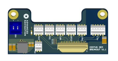
Connection Layout
The following illustration shows the connection locations on the Certus OEM unit.

Certus OEM Breakout Connector Locations
Connection Schematic
The following illustration shows the schematic of the breakout connections.

Certus OEM Connection Schematic
Electrical Connectors
The following table describes the function of each connection and the type and ordering information for connection. Certus OEM PCB Connector is the connector supplied on the Certus OEM PCB ready for customer connection. Mating Connector for Cables is the manufacturers mating connector and part number, plus the part number for a pre-crimped 15 cm cable.
This information is provided to make it easier for you to design the appropriate type and length of connections for your specific application. To make development easier, we also provide standard ~30 cm pre-prepared as described in section Part Numbers and Ordering Options.
| Label | Function | Certus OEM PCB Connector | Mating Connector for Cables |
|---|---|---|---|
| 9-30 V | 9-30 V DC input power | JST 2 pin B2B-XH-AM | JST XHP-2 (Precrimped wires: JST ASXHSXH22K305) |
| 5 V | 5 V DC input power | Molex 2 pin 0874370273 | Molex 0874390200 (Precrimped wires: Molex 0797580016) |
| PRI | Primary Serial UART | Molex 3 pin 0874370373 | Molex 0874390300 (Precrimped wires: Molex 0797580016) |
| AUX | Auxiliary Serial UART | ||
| 1PPS | 1PPS communications | ||
| CAN | CAN Communications Bus | ||
| GPIO | General Purpose Input/Output | ||
| ETH | Ethernet network connectivity | Molex 5 pin 0874370573 | Molex 0874390500 (Precrimped wires: Molex 0797580016) |
| PRIM | Primary GNSS antenna | Female MMCX | Male MMCX RF Connector |
| SEC | Secondary GNSS antenna | Female MMCX | Male MMCX RF Connector |
Connector Descriptions
Connector Pin Allocation
The following table shows the relevant pin allocation for each connection.
Note: Take care to accurately identify Pin 1 (dot / + symbols) when making cables / connections. Always check the print on the PCB to be sure.
Certus OEM Breakout Board
| Connection | Pin | Function |
|---|---|---|
| Power Input 9-30 V | 1 / + | Supply Voltage |
| 2 / - | Ground | |
| 5 V | 1 | Optional 5 V input, see Power Supply |
| 2 | Ground | |
| Primary PRI |
1 | Ground |
| 2 | Primary UART transmit | |
| 3 | Primary UART receive | |
| Auxiliary AUX |
1 | Ground |
| 2 | Primary UART transmit | |
| 3 | Primary UART receive | |
| 1PPS | 1 | Ground |
| 2 | 1PPS | |
| 3 | No Connection | |
| CAN | 1 | Ground |
| 2 | CANL | |
| 3 | CANH | |
| GPIO | 1 | Ground |
| 2 | GPIO1 | |
| 3 | GPIO2 | |
| Ethernet ETH |
1 | Transmit positive + |
| 2 | Transmit negative - | |
| 3 | Receive positive + | |
| 4 | Receive negative - | |
| 5 | Ground |
Connector Pin Allocation
Interoperability with Different Voltage Systems
All signals are 3.3 volt level, however inputs are tolerant to 5 volt signals from the target interface. If you require a different voltage level to be compatible with your target system it is recommended that you install a voltage level translator between the signals of each device.
MMCX RF Connector
The CertusOEM antenna connections are through MMCX connectors on the board. It is recommended to use a MMCX to SMA adapter cable to allow connection to standard GNSS antennas. The MMCX connector is fragile and should be handled with care. It is not designed for repeated connection and disconnection.