Configuration Menu
The Configuration menu contains a number of dialogues for the configuration of Certus Mini.
Manager Configuration Menu
Configuration Export
The Configuration Export dialogue can be used to export all the Certus Mini settings to a file. This file can be imported at a later date or on other units. This is useful to restore a unit to a pre set configuration at a later date or for batch configuration of multiple units.
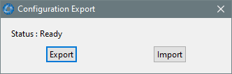
Manager Configuration Export Dialogue
Sensor Ranges
The Sensor Ranges dialogue is used to set the dynamic range of the sensors. If the user is experiencing over-range events during operation, these settings should be used to increase the range of the sensor which is reporting the over-range. The lowest ranges give the best performance, the user should make changes slowly and monitor the results.
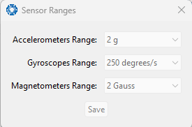
Manager Sensor Ranges Dialogue
Filter Options
For most applications the default filter options should be used and only the vehicle profile set. If in doubt please contact support@advancednavigation.com.
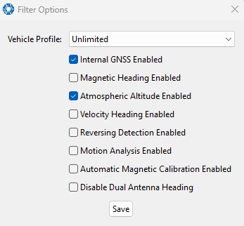
Manager Filter Options
Packet Rates
The Packet Rates dialogue allows the user to specify which packets output on a periodic basis and at what rate. The default packets enabled are the System State Packet (ID 20) and the Raw Sensors Packet (ID 28) at 20Hz and these typically provide all the data that a user will require. These two packets need to be enabled for the data graphs to update in Certus Mini Manager. Other state packets can be enabled as required.
Note: Packet rate configuration applies only to the data port which the Manager is connected to. To configure other ports, the Manager must be connected to that port.
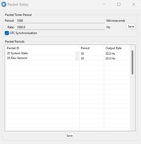
Manager Packet rates
Alignment
The Alignment dialogue is used to set the alignment offsets of the system installation. It is important to set the values in this dialogue correctly for accurate results.
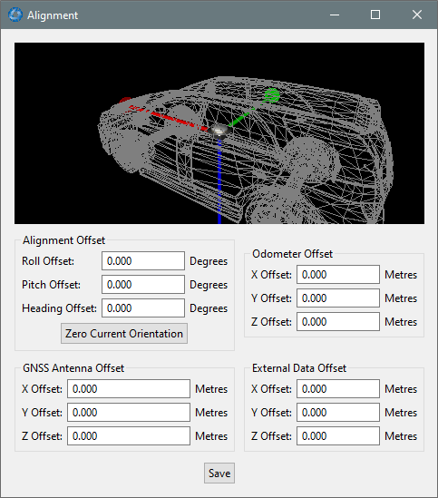
Manager Alignment Dialogue
Alignment Offset
If Certus Mini is installed into the vehicle with the positive X-axis pointing forwards and the positive Z-axis pointing down, then no alignment offset is required and the roll, pitch and heading offset values can remain at the factory defaults of zero.
If the unit is installed in a different orientation then the roll, pitch and heading offset must be entered. For example if the unit is installed on its side with the X-axis pointing up and the Z-axis pointing forwards and no change to the Y-axis, then this would result in a pitch offset of +90 degrees with roll and heading remaining zero.
If there is a small misalignment due to mechanical mounting error this can be compensated for by setting the vehicle stationary on a level surface and pressing the Zero Current Orientation button.
Note: Zero Current Orientation will only correct for roll and pitch offsets, the Heading offset must be entered manually and saved before using this function.
All the other offsets will be measured in the realigned body co-ordinate frame (X positive forward, Z positive down) after being corrected for any alignment offset entered.
GNSS Antenna Offset
The GNSS antenna offset is measured from the centre of the Certus Mini unit to the phase centre of the primary antenna in the orientation of the The Body Co-ordinate Frame (X positive forward, Z positive down).
Odometer Offset
The odometer offset is measured from the centre of the Certus Mini unit to the point at which the vehicle's tyre being measured makes contact with the road in the body co-ordinate frame (X positive forward, Z positive down).
If your odometer is not measuring a specific wheel, the offset should be to the point on the ground beneath the measurement point. If, for example, your car is a front wheel drive and you are using the velocity from the car OBDII port, the measurement point would be midway between the two front wheels.
External Data Offset
These values are only required for specialty applications operating with an external source of velocity data. The offsets are used when providing NMEA Input, External GNSS, or with an Air Data Unit. When using a DVL, use the odometer offset. Contact support@advancednavigation.com for assistance with these values.
Port Mode and Baud Rates
Some machines running Microsoft Windows do not support higher baud rates. When changing baud rates, it is recommended to test the baud rate configuration first, without ticking the Permanent box. This way, if it is not possible to communicate at the higher baud rate, a power cycle can be used to revert to the previous baud rate setting.
The factory default baud rate value for these ports is 115200 bps.
Note: The primary and auxiliary ports on Certus Mini OEM are UART only, and cannot be changed to RS232 or RS422. An appropriate adapter/interface is required to connect to a computer.
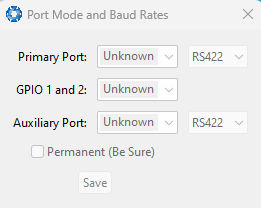
Manager Baud Rates Dialogue
GPIO
This page allows the user to configure the input and output functions of the
Note: The GPIO port functions at RS232 levels for data functions and 0 to 5 volt (or 0 to 3.3 V) levels for all other functions. The auxiliary port functions at
The default values for these settings are Inactive.
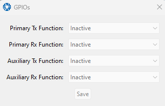
Manager GPIO configuration Dialogue
Odometer
The Odometer dialogue allows the user to configure the odometer pulse length and view the real time odometer data to verify correct operation. See Odometer and Odometer Pulse Length for more information on the use of odometers. The odometer offset is also applied when using a DVL input.
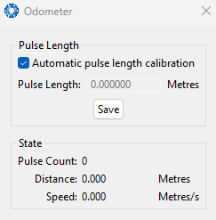
Manager Odometer Dialogue
Reset
The Reset button causes the system to perform a power cycle. No configuration settings or state data are lost. The Cold Start button clears all filters, and connections are reset and must re-established. No configuration settings are lost. The Factory Restore button resets all Certus Mini settings back to their factory defaults, including state data and all configuration settings. It also erases the hot start data so that the system is forced to perform a cold start.
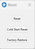
Manager Reset Dialogue
Reference Position Offsets
The Reference Point Offsets dialogue allows the user to set measurement points away from its default position at the physical centre of the Certus Mini unit. The primary reference point offset applies to data from all ANPP packets as well as all peripheral output such as NMEA messages and Heave Point 1.
When the values are zero the measurement point is the centre of the Certus Mini unit. This can be offset to a different position on the profile by entering the offset value from the centre of the Certus Mini unit to the desired position in the body co-ordinate frame (X positive forwards, Z positive down).
Note: These values only apply to the Heave Packet. NMEA, TSS and Simrad heave is not affected by the values in this dialogue which are always measured at the centre of the Certus Mini unit.
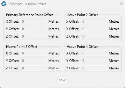
Manager Reference Position Offset
GPIO Output
The GPIO output configuration dialogue allows the user to configure the NMEA0183, TSS1 and SIMRAD output rates for the
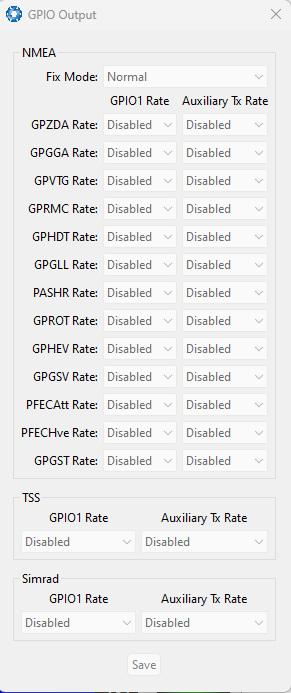
Manager GPIO Output Dialogue
Manual Initialisation
The Manual Initialisation dialogue can be used to manually initialise Certus Mini when a GNSS fix is not available. Setting the position will initialise the navigation filter. Setting the heading will also initialise the heading filter.
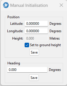
Manual Initialisation Dialogue
Dual Antenna
Where dual GNSS antenna input is supported, the Dual Antenna configuration page is only used if the primary and secondary GNSS antennas are not installed in their recommended and default positions of primary front and secondary rear, at the same height. If it is not practical to mount the antennas in the recommended alignment, the alternate alignments must be entered into this page. It is recommended to try and use one of the automatic offsets where possible, where the antennas must be installed in one of four different automatic offset orientations aligned on an axis. If it is not possible to use one of the automatic offsets, the antennas can be installed in any configuration and a manual offset should be entered. The manual offset is measured from the central base of the secondary antenna to the central base of the primary antenna in the body co-ordinate frame (X+ forward, Z+ down). If using a manual offset, be careful to measure the offset accurately, as even small offset errors can result in relatively large heading errors e.g. 2 cm error = 1.15 degrees heading error with a 1 metre separation.
- When using an automatic offset, the manual offset values are ignored.
- When using a manual offset, the automatic offset selection is ignored.
- When using automatic offset, the manual offset values will show the distance that Certus Mini has automatically measured.
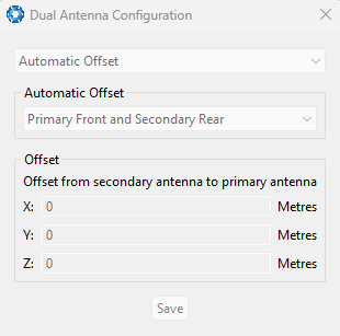
Manager Dual Antenna Dialogue
Gimbal
The Gimbal configuration dialogue is only used in gimbal specific applications.
Contact support@advancednavigation.com for more information on using Certus Mini inside a gimbal.
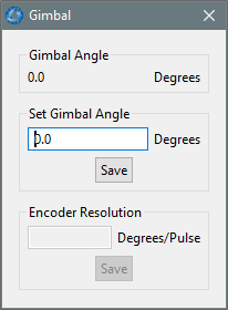
Manager Gimbal Dialogue
GNSS Configuration
The GNSS Configuration dialogue allows the user to select constellation configurations based on the type of GNSS receiver installed. If an invalid configuration is entered, the system will revert to the previous configuration when attempting to save changes.
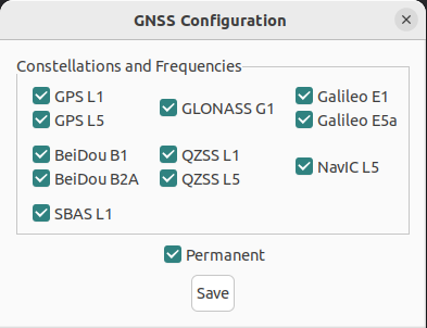
Manager GNSS Configuration Dialogue
The following configuration rules are applicable:
- By default:
- GPS, Galileo and GLONASS constellations are enabled.
- SBAS and QZSS correction services are enabled.
- When selecting a GNSS constellation, all frequencies for that constellation must be selected, with the exception of GPS and Beidou.
- GPS and Beidou can be enabled with L1/B1 frequency only, and a second frequency is optional.
- SBAS and QZSS correction services can be enabled for any constellation configuration as long as GPS L1 is enabled.
The table below lists the supported constellations and the corresponding GNSS sample rate depending upon the number of constellations selected. When setting the data ports, the packet rate of the Raw Satellite Data Packet is automatically adjusted to the next lower integer multiple of the sample period.
| # of Constellations | Constellation Configurations | Packet Period | Packet Rate |
|---|---|---|---|
| 1 | GPS |
40 ms | 25 Hz |
| BDS, GLO, GAL, NVC | 50 ms | 20 Hz | |
| 2 | GPS + GLO |
67 ms | 15 Hz |
| GPS + GAL | 72 ms | 14 Hz | |
| All other combinations | 100 ms | 10 Hz | |
| 3 | All combinations | 125 ms | 8 Hz |
| 4 | All combinations | 143 ms | 7 Hz |
| 5 | All combinations | 200 ms | 5 Hz |
Supported constellations and the corresponding GNSS sample rate
CAN Settings
The CAN Settings page allows you to enable or disable the CAN functionality. If the user is connecting to Certus Mini via the primary port then these settings can be ignored. The default for CAN is Enabled at 1,000,000 baud rate. A CANOpen EDS file is available. Contact support@advancednavigation.com to obtain a copy of this file.
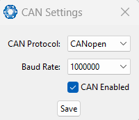
Manager CAN Settings Dialogue