Schematics
Dual RS232 Transceiver
![]()
Diagram: Dual RS232 Transceiver schema
M3 standoffs
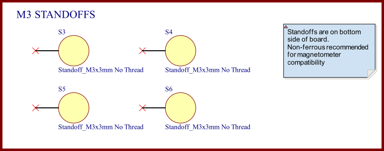
Diagram: M3 standoffs schema
OEM Dev Board Interfaces
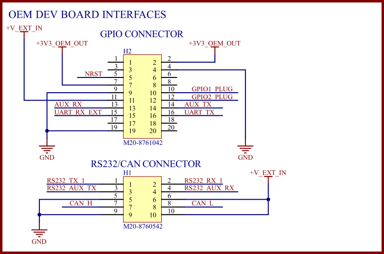
Diagram: OEM Dev Board Interfaces schema
OEM Board to Board Connector
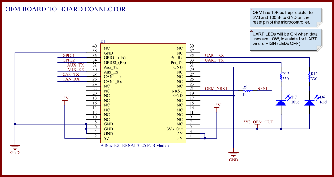
Diagram: OEM Board to Board Connector schema
Refer to the table below for the connector pin numbering.
| Pin | Function |
|---|---|
| 1, 2, 3 | + Power Supply |
| 4, 6, 8, 19, 31, 38 | - Ground |
| 33 | Prim Tx |
| 35 | Prim Rx |
| 32 | Aux Tx |
| 30 | Aux Rx |
| 26 | CAN Rx (Not CAN Hi/CAN Lo) |
| 28 | CAN Tx (Not CAN Hi/CAN Lo) |
| 36 | GPIO1 |
| 21 | NRESET |
| 5 | 3V3 Out for logic voltage translators |
| 34 | GPIO2 |
| A1 | U.FL (Primary antenna) |
| B2 | U.FL (Secondary antenna) |
Table: Pin allocation for OEM Board Connector
OEM M1.6 Standoffs
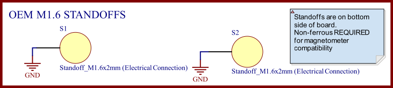
Diagram: OEM M1.6 Standoffs
GPIO Protection
Users should ensure that any signals that are connected externally from the PCB, including GPIO and UART pins, are adequately protected. The use of a series Schottky diode and 1k resistor should provide sufficiently robust protection for the majority of use cases.
External interface pins on Certus Mini have on chip pull-up/pull-down resistors enabled to avoid signals oscillating when not connected. The user shouldn't need to place any pull-up or pull-down resistors on their PCB.
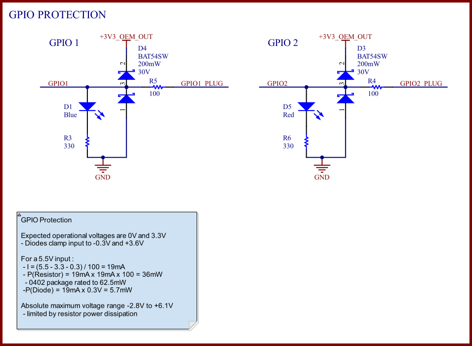
Diagram: OEM external signal protection example schema.
Switchable Power Input
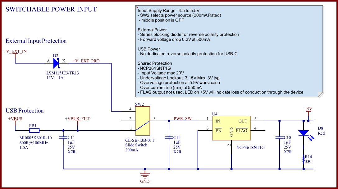
Diagram: Switchable Power Input schema.
USB C Connector
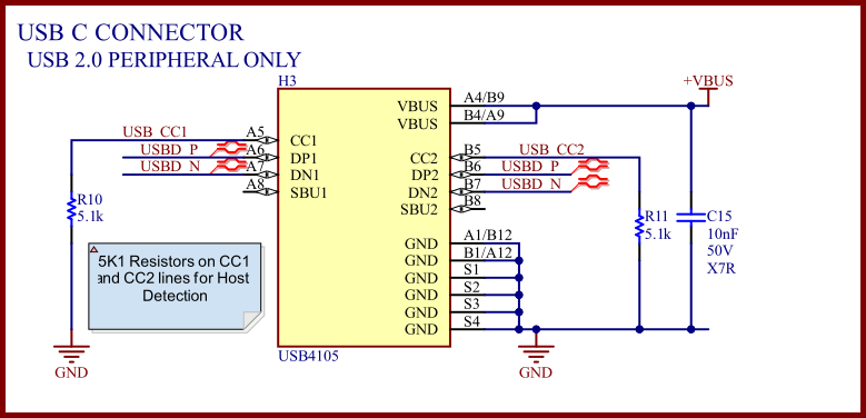
Diagram: USB C Connector schema.
User Configuration Switches
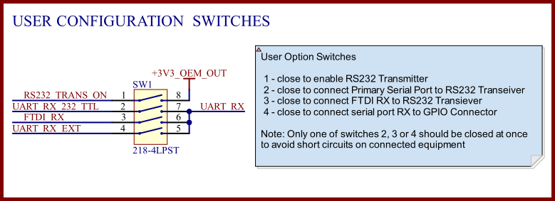
Diagram: User Configuration Switches schema.
CAN Transceiver
![]()
Diagram: CAN Transceiver schema.
FTDI USB to UART
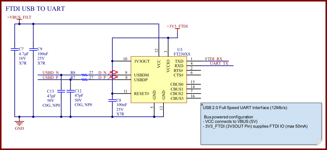
Diagram: FTDI USB to UART schema.