GNSS Antenna Installation
Correct antenna placement and configuration are critical for achieving accurate positioning with an Inertial Navigation System (INS). It involves maximising signal reception and minimising signal loss. Recommendations vary slightly depending on whether your device uses standard or anti-jam GNSS receivers.
General Placement Requirements
-
Ensure a Clear View: Install the antennas level with respect to each other, ensuring a clear, unobstructed view of the sky down to the horizon.
-
Mitigate Interference: Mount the antennas away from reflective surfaces to reduce multipath interference.
-
Avoid RF Emitters: Position the antennas away from powerful Radio Frequency (RF) emitters, such as radars, high-powered communication links, or high-current wiring.
-
Use a Ground Plane: Place the antenna over a flat, conductive ground plane (such as a piece of plate aluminium). The minimum recommended ground plane radius is 60 mm, or as specified by the antenna supplier.
-
Ensure Stability: Securely mount the antenna to prevent movement or vibration.
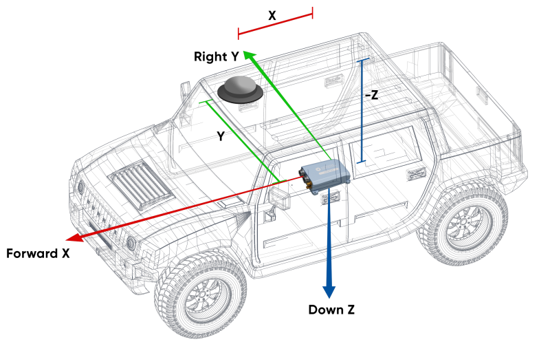
Antenna Offset Isometric View
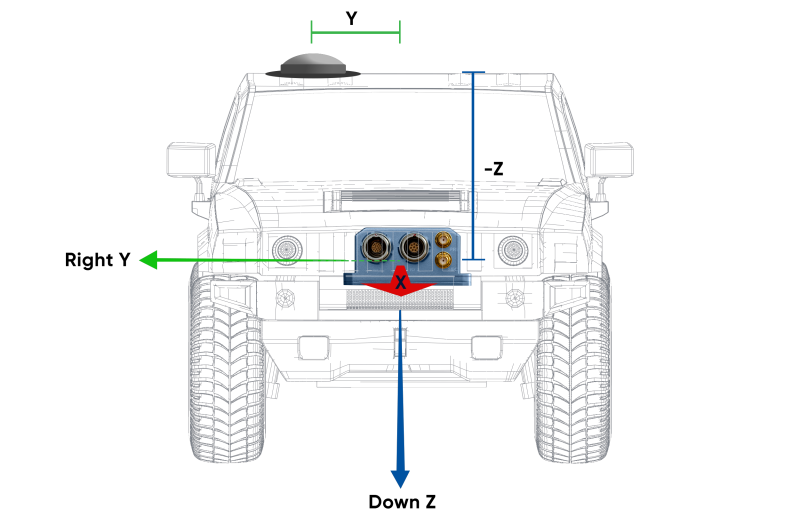
Antenna Offset Front View
Dual-Antenna Heading Configuration
For systems utilizing dual-antenna heading, precise configuration is key.
-
Configure Primary Antenna Offset: Accurately configure the physical offset from the INS unit's centre to the primary GNSS Antenna Reference Point (ARP) in the system's software (Web UI or Manager). The offset is measured in the body coordinate frame: X+ forward, Z+ down.
-
Note: The Z-axis is positive downwards. Mounting the antenna above the INS unit requires a negative Z offset.
-
Note: An inaccurate offset leads to performance degradation during angular rotations and turns because the INS cannot correctly compensate for lever arm velocities.
-
-
Position Secondary Antenna: Ideally, mount the secondary antenna directly behind the primary antenna, in line with the vehicle's long axis.
-
Maximize Separation: Increase the antenna separation distance whenever possible, as greater separation directly improves heading accuracy.
-
Verify Phase Centre: Ensure the antenna has an accurate phase centre. This is required for correct dual-antenna heading functionality and RTK capability.
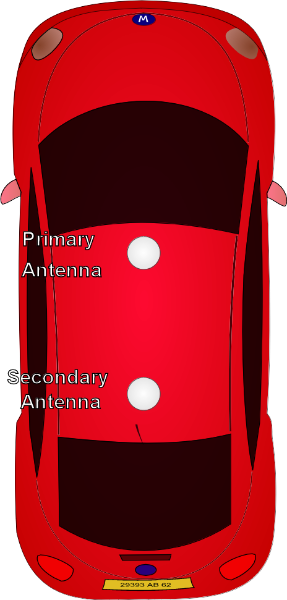
Recommended Second Antenna Placement
Anti-Jam Antennas
Anti-Jam (AJ) antennas have stricter and slightly differing requirements which extend or slightly override standard GNSS antenna instructions. Anti-jam antennas filter interference by shaping their radiation pattern and so are very sensitive to mounting geometry. Consequently, you should closely follow the manufacturer’s specific guidelines.
Calian AJ977XF Mounting Recommendations
-
Ground Plane Diameter: Use a ground plane with a diameter of 30 cm or less to maintain the integrity of the radiation pattern.
-
Antenna Mounting Height: Mount the antenna base 25 mm to 50 mm above the ground plane surface.
-
Separation from Ground Plane: Maintain an optimal vertical separation of 25 mm to 50 mm between the bottom of the antenna and the ground plane surface.
-
Ensure Stability: Securely mount the antenna to prevent movement or vibration.
Effects of Incorrect Mounting
Deviating from guidelines significantly degrades anti-jamming performance and overall system accuracy:
-
Pattern Distortion: Oversized ground planes can cause significant changes to the Right Hand Circular Polarisation (RHCP) gain, making it more directive and unstable. Extremely large ground planes can result in the creation of multiple nulls due to side lobes and ripples in both RHCP and Left Hand Circular Polarisation (LHCP) patterns.
-
Increased Multipath Susceptibility: Larger ground planes cause the LHCP gain at and above the horizon to generally increase. This gain results in degradation of the axial ratio, amplifying reflected signals, making the system more vulnerable to position errors in reflective environments. This leads to high susceptibility to multipath interference.
-
Null Shift: Increasing the ground plane diameter shifts the intended filtering null down in elevation (approximately 5° for every 15 cm diameter change). This alters the antenna's protection zone, potentially reducing jammer rejection capability or blocking desired satellite signals.
Antenna Cables
Proper cable management minimizes signal loss and protects the system from interference.
-
Cable Length: Try to keep the antenna cables the same length and as short as possible for the application.
-
Route Safely: Route cables away from powerful RF emitters, high current wiring, high temperatures, and machinery. Do not coil excess cable; find the shortest viable run.
-
Bending: Do not bend the cable tighter than its minimum bend radius, and prevent denting. Secure cables using wide, loosely fixed cable ties.
-
Connectors: Use recommended antenna cable connectors listed in Part Numbers and Ordering.
-
Signal Loss: Ensure the entire cable run (including all connectors) allows the GNSS receiver to receive a minimum of 33 dB of gain at its connector. Use lower-loss cables (LMR series) for longer runs to meet this requirement.
| Cable Type |
Minimum Bend Radius |
Signal Loss |
|---|---|---|
| RG-58/U Low Loss | 20 mm | ~0.92 dB/m |
| LMR240 | 20 mm | ~0.33 dB/m |
| LMR300 | 22.2 mm | ~0.26 dB/m |
| LMR400 | 25.4 mm | ~0.17 dB/m |
Antenna Suction Cup Mount
Use a suction cup mount when you need to mount antennas temporarily or on surfaces unsuitable for permanent installation.
-
Applicability: Use a suction cup mount when installing antennas at any angle or on smooth, non-porous surfaces, such as a window or vehicle bodies made of aluminium or fibreglass.
-
Benefit: This type of mount allows for quick attachment and removal.
-
Caution: Ensure the suction cup surface is clean and the seal is maintained during operation.