Connector Pin-out
Power supply and signal connections are made through the two push-pull type connector – one has 8 pins, the other has 16 pins. The connectors provide reliable and rugged connections to Certus under demanding conditions and are rated to IP67 in the mated position.
Advanced Navigation produces tested cable assemblies as either a breakout cable (see 8 Pin IO Breakout Cable and 16 Pin IO Breakout Cable), or a 3 metre or 10 metre unterminated cable (see Part Numbers and Ordering). Advanced Navigation supplied cable assemblies are shielded TPE cable, with each individual wire colour-coded FEP coated 24 AWG wire (for the 8 pin cable) or 28 AWG wire (for the 16 pin cable).
If sourcing and assembling your own cables, the connectors are interchangeable across different manufacturers as detailed below:
| Connector | Manufacturer & Series | Part Number | Notes |
|---|---|---|---|
| 8 pin circular pushpull connector plug | LEMO K | FGG.1K.308.CLAC60Z | Size 1 1 key |
| ODU MINI-SNAP K | S11K0C-P08MFG0-6000 | ||
| Amphenol FLO K | FLKC-08FGMS-GCP-213 | ||
| 16 pin circular pushpull connector plug | LEMO K | FGA.1K.316.CLAC60Z | Size 1 2 key |
| ODU MINI-SNAP K | S11KAC-P16MCC0-6000 | ||
| Amphenol FLO K | FLKC-16FGMS-ACP-213 |
Note: Both of the two connectors have a power supply connection. Only one of these power supplies should be connected. Connecting two different power supplies could result in damage to the unit.
Certus features galvanic isolation between different pins to prevent interference. This means that there are different grounds that apply for different pins. See Electrical Domains for more information on the different ground domains.
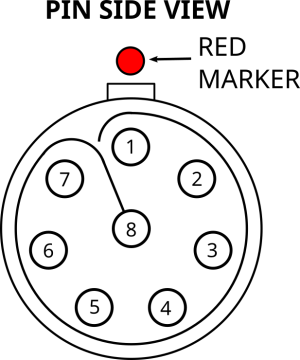
8 Pin Connector
See 8 Pin Harness connector pin locations below for pin locations. The image is a pin side view, meaning a view looking into the pins on the harness connector.

8 Pin Plug with Unterminated Connectors
| Pin | Colour | Function |
|---|---|---|
| 1 | Black | Power Ground (see Electrical Domains) |
| 2 | Red | Power Supply |
| 3 | Grey / Black Stripe | 1PPS |
| 4 | White / Green Stripe | Ethernet T+ |
| 5 | Green | Ethernet T- |
| 6 | White/Orange Stripe | Ethernet R+ |
| 7 | Orange | Ethernet R- |
| 8 | Grey | 1PPS (GPIO) Ground (see Electrical Domains) |
| Housing | Cable Braided Shield | Chassis Ground (see Electrical Domains) |
Pin Allocation for 8 Pin Connector
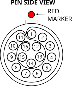
16 Pin Connector
See 16 Pin Harness connector pin locations below for pin locations. The image is a pin side view, meaning a view looking into the pins on the harness connector.

Certus 16 pin plug with Unterminated Connectors
| Pin | Colour | Function |
|---|---|---|
| 1 | Black | Power Ground (see Electrical Domains) |
| 2 | Red | Power Supply |
| 3 | Violet | Primary RS422 Tx+ / RS232 Tx |
| 4 | Violet / Black Stripe | Primary RS422 Tx- |
| 5 | Yellow | Primary RS422 Rx+ / RS232 Rx |
| 6 | Yellow / Black Stripe | Primary RS422 Rx- |
| 7 | Light Brown | CAN L |
| 8 | Light Brown / Black Stripe | CAN H |
| 9 | Blue | GPIO 1 |
| 10 | Grey | GPIO Ground (see Electrical Domains) |
| 11 | Brown | GPIO 2 |
| 12 | Light Blue | Auxiliary RS422 Tx+ / RS232 Tx |
| 13 | Light Blue / Black Stripe | Auxiliary RS422 Tx- |
| 14 | Light Green | Auxiliary RS422 Rx+ / RS232 Rx |
| 15 | Light Green/Black Stripe | Auxiliary RS422 Rx- |
| 16 | White | Serial Ground (see Electrical Domains) |
| Housing | Cable Braided Shield | Chassis Ground (see Electrical Domains) |
Pin Allocation for 16 Pin Connector