Impeller Maintenance
This section of the manual provides a comprehensive guide on Impeller maintenance. It covers safety precautions, the tools and materials needed, detailed procedures for thruster change-outs and cleaning and inspection guidelines. By following these guidelines, operators can ensure Hydrus continues to perform at its best in all underwater operations.
Note: Hydrus hardware v1.1 uses simpler universal impellors, instead of clockwise/counter-clockwise impellors used by Hydrus hardware v1.0. Diagrams and instructions within this section show the hardware v1.1 impellors, but otherwise the instructions are the same.
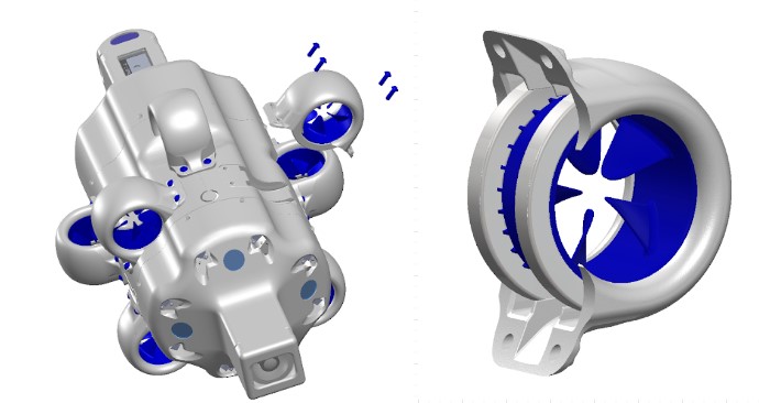
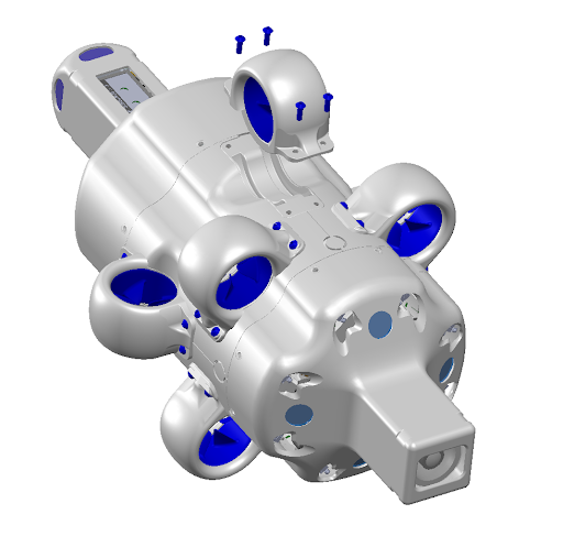
Thruster Assembly Exploded
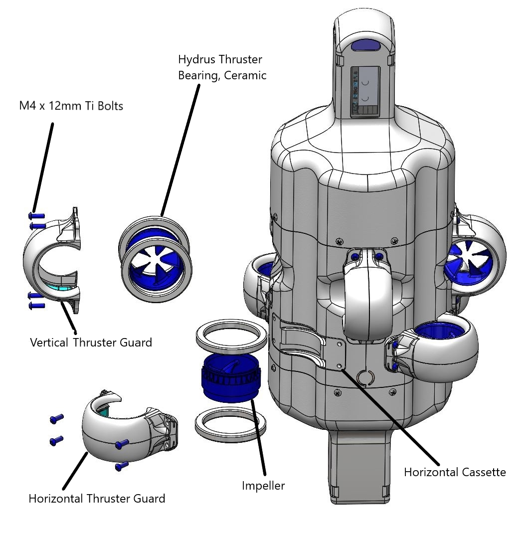
Thruster Assembly Exploded
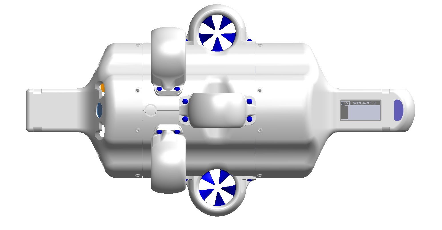
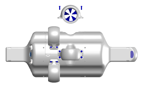
Thruster Layout
Note: Hydrus hardware v1.1 uses simpler universal impellors, instead of clockwise/counter-clockwise impellors used by Hydrus hardware v1.0. Diagrams and instructions within this section show the hardware v1.1 impellors, but otherwise the instructions are the same.
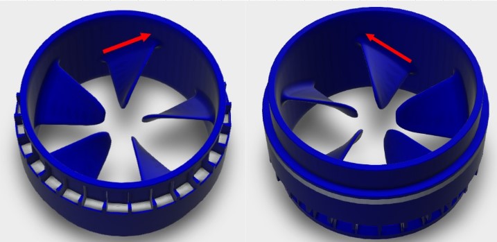
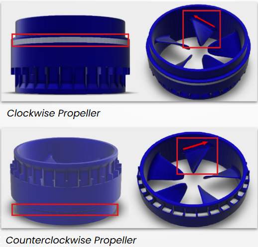
Clockwise (CW) Impellor
The CW Impellor can be denoted by a white ribbon around it's surface and the base of the impellor blade inclines towards the left.
Note: The CW Impeller can be inserted into the thruster guard either way up (white line up or down), there is no significance.
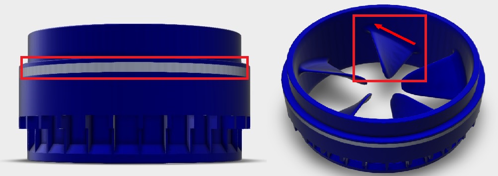
CW Top View Side View
Counter Clockwise (CCW) Impellor
The CCW Impellor can be denoted by no ribbon on the surface of the impellor and the impellor blade base leans outwards towards the right.
Note: The CCW Impeller can be inserted into the thruster guard either way up, there is no significance.
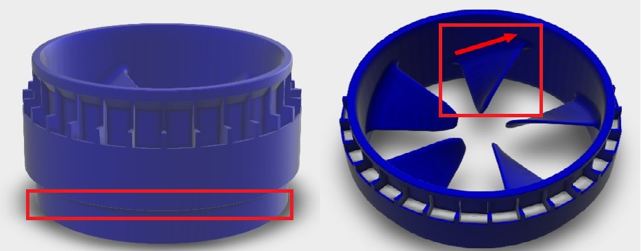
CCW Top View Side View
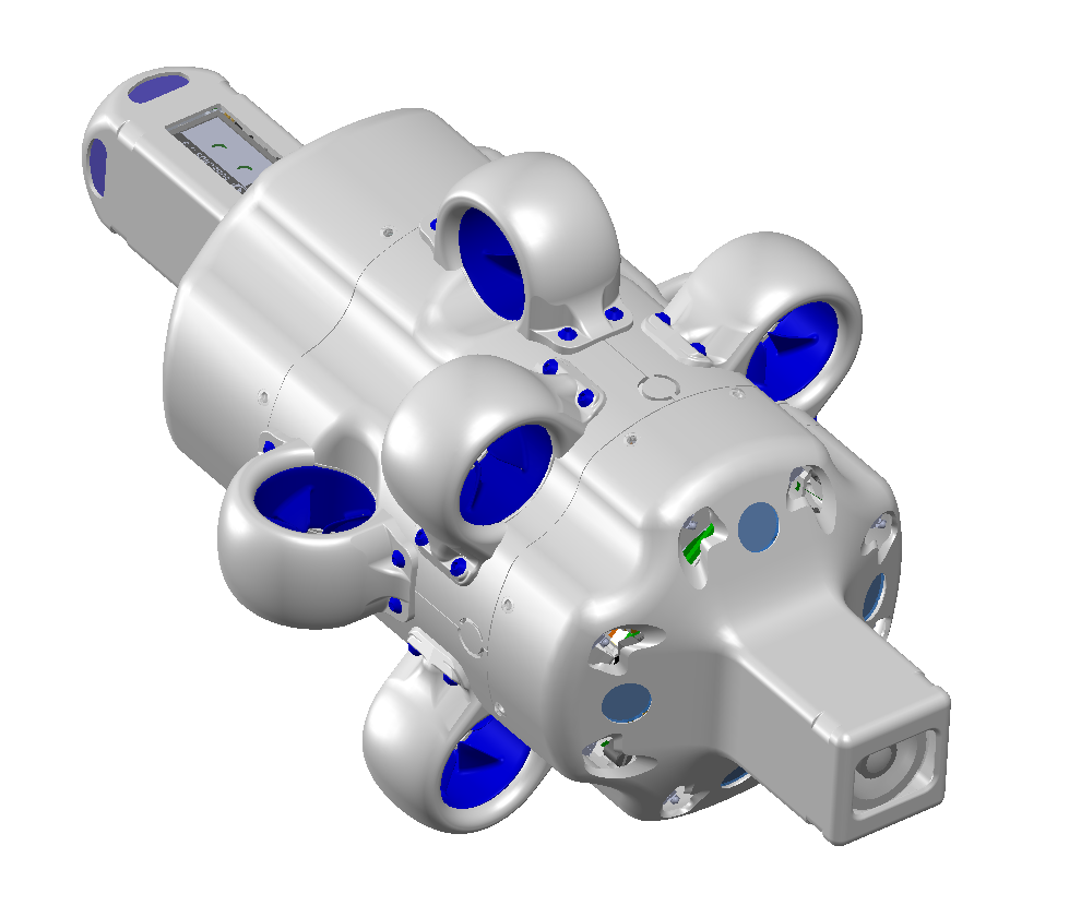
Thruster Layout Complete

Thruster Layout Complete
Note: The following table applies to Hydrus hardware v1.0. Hydrus hardware v1.1 uses simpler universal impellors, instead of clockwise/counter-clockwise impellors used by Hydrus hardware v1.0.
| Thruster Number | Impellor Direction | Guard Type |
|---|---|---|
| 0 | Counter Clockwise (CCW) | Horizontal Guard |
| 1 | Clockwise (CW) | Horizontal Guard |
| 2 | Counter Clockwise (CCW) | Horizontal Guard |
| 3 | Clockwise (CW) | Horizontal Guard |
| 4 |
Clockwise (CW) |
Vertical Guard |
| 5 |
Counter Clockwise (CCW) |
Vertical Guard |
| 6 | Counter Clockwise (CCW) | Vertical Guard |
Horizontal Thruster Guard
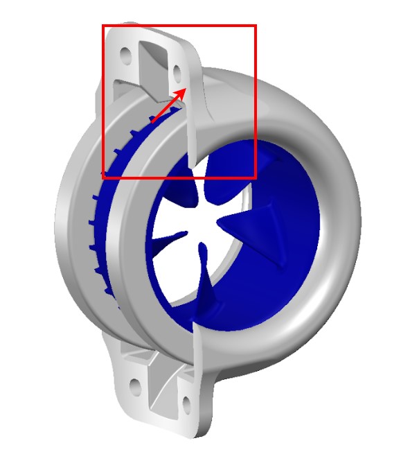
The Horizontal Thruster Guard is a protective component designed to prevent damage to the thrusters of the Hydrus. The Horizontal Thruster Guard is characterised by a curvature of the base of the guard that aligns with the main body of Hydrus, the guard will house in the shallow cassette on the Hydrus which is depicted in the illustration below.
Horizontal Thruster Guard
Vertical Thruster Guard
The Vertical Thruster Guard's design is distinct from the Horizontal Thruster Guard. While the Horizontal Thruster Guard is characterised by a curvature that aligns with the main body of Hydrus, the Vertical Thruster Guard has a base that is near straight and will sit in the deeper cassette on the Hydrus main body. see below for illustration.
Hydrus Flat Surface
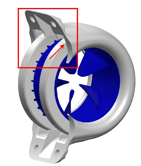
Ceramic Bearings
The ceramic bearing is a disc-shaped assembly composed of a hollow ceramic ring. This ring includes an inner and outer raceway that encapsulates extremely hard and smooth ceramic balls. Each thruster assembly requires two of these ceramic bearings. They are positioned on either side of the impellor and are fit between the thruster guard and the thruster cassette.
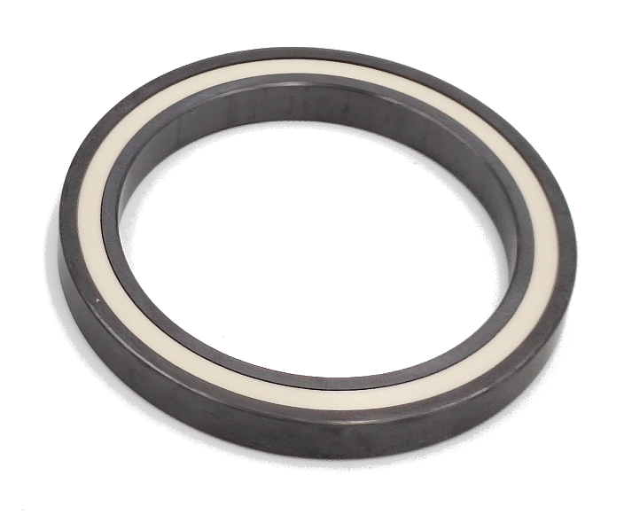
Ceramic Bearing
Tools and Materials Needed
| Item | Quantity |
|---|---|
| 2.5mm Hex Head | 1 |
| Horizontal / Vertical Guard | 1 |
| Clockwise (CW) / Counterclockwise (CCW) Impellor | 1 |
| M4 x 12mm Bolts | 4 |
| Hydrus Thruster Bearing, Ceramic | 2 |
Thruster Guard Removal: Using the 2.5mm hex key, carefully unscrew the four M4 x 12mm Ti thruster guard screws. Keep these screws in a safe place for reassembly.
Hydrus Vertical Thruster Removal
Thruster Removal: Gently detach the thruster guard from the main body of the Hydrus. This should require minimal force. The impellor and the ceramic bearing are housed within the thruster guard.
Thruster removal
Component Separation: Separate the impellor and the ceramic bearing located inside the thruster guard. Further dismantle the two ceramic bearings from the impellor by gently pulling around the collar of the bearing
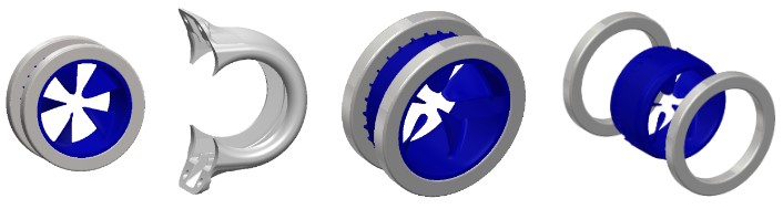
Impellor Assembly Separated
Note: Thoroughly inspect the thruster guard, the two ceramic bearings, thruster guard and the impellor for any signs of damage. Replace any components as necessary.
Note: It's crucial to handle ceramic bearings with care, as dropping them could result in damage, potentially rendering them unusable.
Note: Exercise caution to avoid applying any pressure on the impeller blades while extracting the bearings.
Impellor Identification (only applicable for legacy Hydrus hardware v1.0): Determine whether the impellor being replaced is a CW (Clockwise Impellor) or a CCW (Counter Clockwise Impellor).
Impellor Identification
Reassembly: Reattach the two ceramic bearings to the impellor and slide the assembly back into the thruster guard.
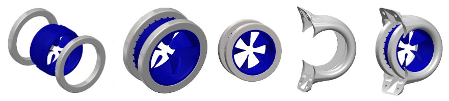
Thruster Re Assembly
Thruster Replacement: Carefully align and reattach the thruster guard to the main body of the Hydrus. Ensure that the thruster assembly is properly seated in the cassette. Insert and hand-tighten the thruster guard screws. By hand, test spin the newly mounted thruster assembly to ensure smooth and free rotation. If required, adjust tension on the mounting bolts to ensure on cross-torque is being applied to the guard that may prevent the Impeller from spinning.
Note: Adjust the torque on the mounting bolts as needed to prevent the force on the guard from obstructing the impeller's spin.
Thruster Replacement
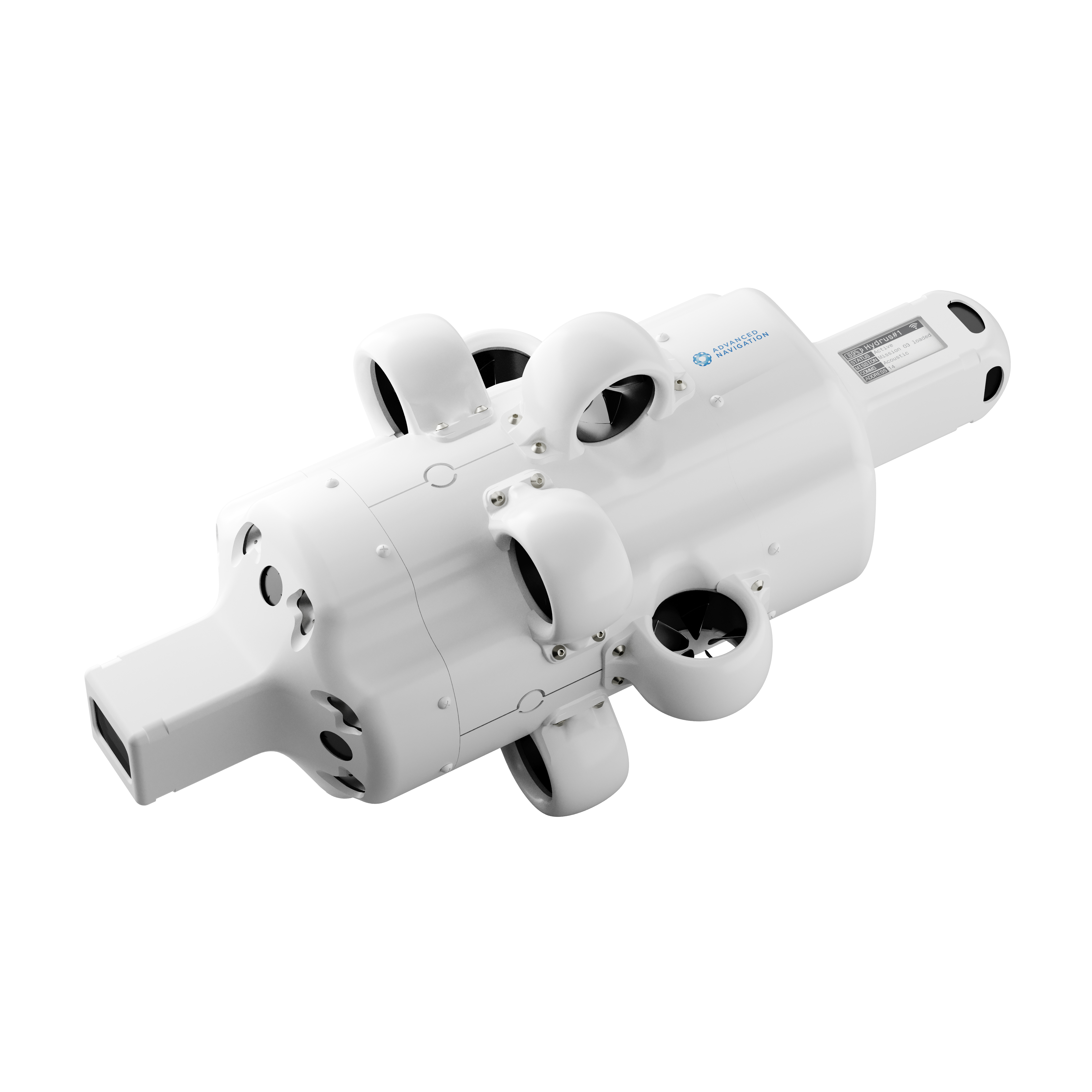
Hydrus Complete
Note: Self-Test: After the thruster has been replaced and secured, conduct a Testing and Functional Checks to ensure the new thruster is functioning correctly.
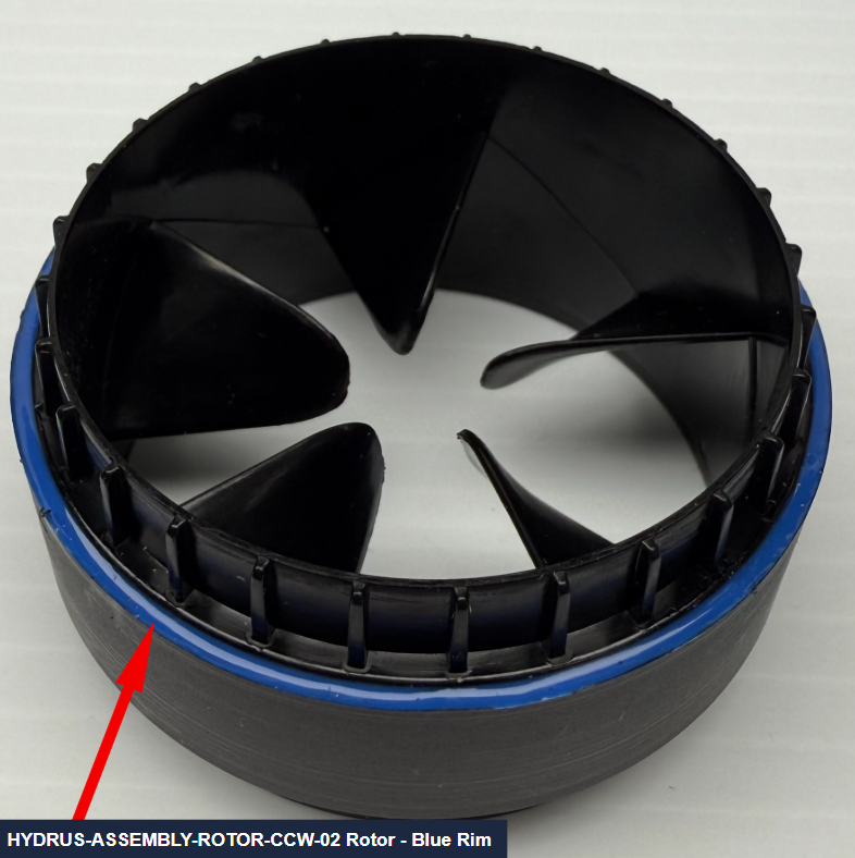
HYDRUS-ASSEMBLY-ROTOR-CCW-02 Injection Molded Rotors
This section showcases the different Hydrus v1.0 & Hydrus v1.1 Rotor versions and defines the workflow for using the updated injection molded HYDRUS-ASSEMBLY-ROTOR-CCW-02 rotors design with Hydrus v1.0 units.
| Hydrus | Works with Rotor Part Numbers: |
|---|---|
| Hydrus v1.0 |
HYDRUS-ASSEMBLY-ROTOR-CCW-02 (current) or HYDRUS-ASSEMBLY-ROTOR-CW (deprecated) + HYDRUS-ASSEMBLY-ROTOR-CCW (deprecated) |
| Hydrus v1.1 | HYDRUS-ASSEMBLY-ROTOR |
Note: The updated HYDRUS-ASSEMBLY-ROTOR-CCW-02 rotors are not compatible with Hydrus v1.1 units, nor are Hydrus v1.1 rotors compatible with Hydrus v1.0 units.
Hardware Descriptions:
Hydrus v1.1 - Product hardware update
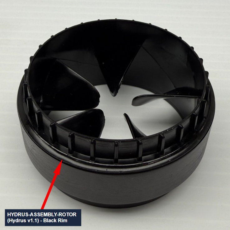
HYDRUS-ASSEMBLY-ROTOR
Hydrus v1.1 units come equipped by default with injection molded rotors, which offer advantages over the deprecated v1.0 rotors, such as:
-
Significantly more resistant to corrosion, thus increased operational life;
-
Minor increase in operational efficiency;
-
One propeller direction, eliminating the need for specific rotor mounting positions.
Hydrus v1.0 - Initial product hardware release
Deprecated v1.0 Rotors - Clockwise & Counter-Clockwise Types
The deprecated v1.0 rotors are separated into two distinct parts:
-
Clockwise: Distinguishable by the white side strip on the outer circumference of the rotor.
-
Counter-clockwise: Distinguishable by the lack of a white side strip on the outer circumference of the rotor.
Updated Rotors HYDRUS-ASSEMBLY-ROTOR-CCW-02 - Only Counter-Clockwise
Hydrus 1.0 now supports improved rotors, part HYDRUS-ASSEMBLY-ROTOR-CCW-02.
Note: Ensure that Hydrus v1.0 units outfitted with HYDRUS-ASSEMBLY-ROTOR-CCW-02 rotors are loaded with v1.61 firmware or above.
Comparisons:
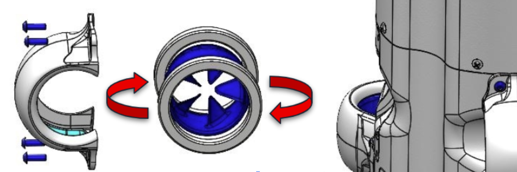
The distinguishing feature between HYDRUS-ASSEMBLY-ROTOR (Hydrus v1.1) & HYDRUS-ASSEMBLY-ROTOR-CCW-02 (Hydrus v1.0) rotors is the presence of a blue rim across the front-facing outer circumference of the HYDRUS-ASSEMBLY-ROTOR-CCW-02 rotors, as pictured below.
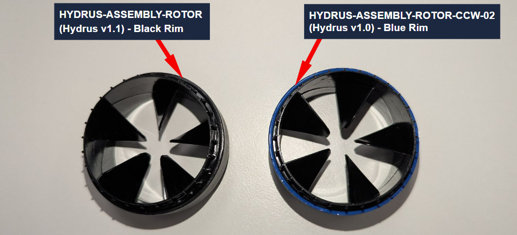
Hydrus version injection molded rotors comparison
Legacy Hydrus v1.0 units benefit from HYDRUS-ASSEMBLY-ROTOR-CCW-02 rotors, to be installed by the user, which provide the same advantages provided by v1.1 rotors:
-
Significantly more resistant to corrosion, thus increased operational life;
-
Minor increase in operational efficiency;
-
One propeller direction, eliminating the need for specific rotor mounting positions.
Note: Ensure that Hydrus v1.0 units outfitted with HYDRUS-ASSEMBLY-ROTOR-CCW-02 rotors are loaded with v1.61 firmware or above.
Note: Ensure that Hydrus v1.0 units are only outfitted with a single version of rotors at one time.
Note: All rotor types/versions can be mounted in either direction to their respective receiving Hydrus versions' thruster sockets.
Firmware update workflow for v1.0 units
Note: Ensure Hydrus v1.0 units are loaded with v1.61 Hydrus firmware.
After outfitting Hydrus v1.0 units with HYDRUS-ASSEMBLY-ROTOR-CCW-02 thrusters, navigate to the ‘Tools’ → ‘Licenses’ menu.
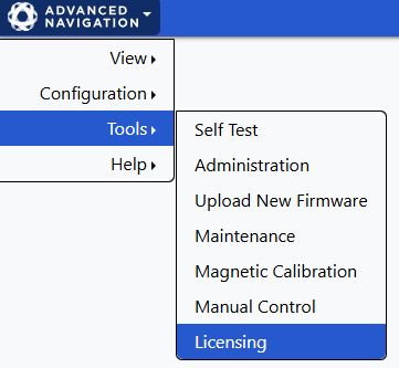
Under ‘Persistent Settings’, enable the ' HYDRUS-ASSEMBLY-ROTOR-CCW-02 Thruster Rotors Installed' option.
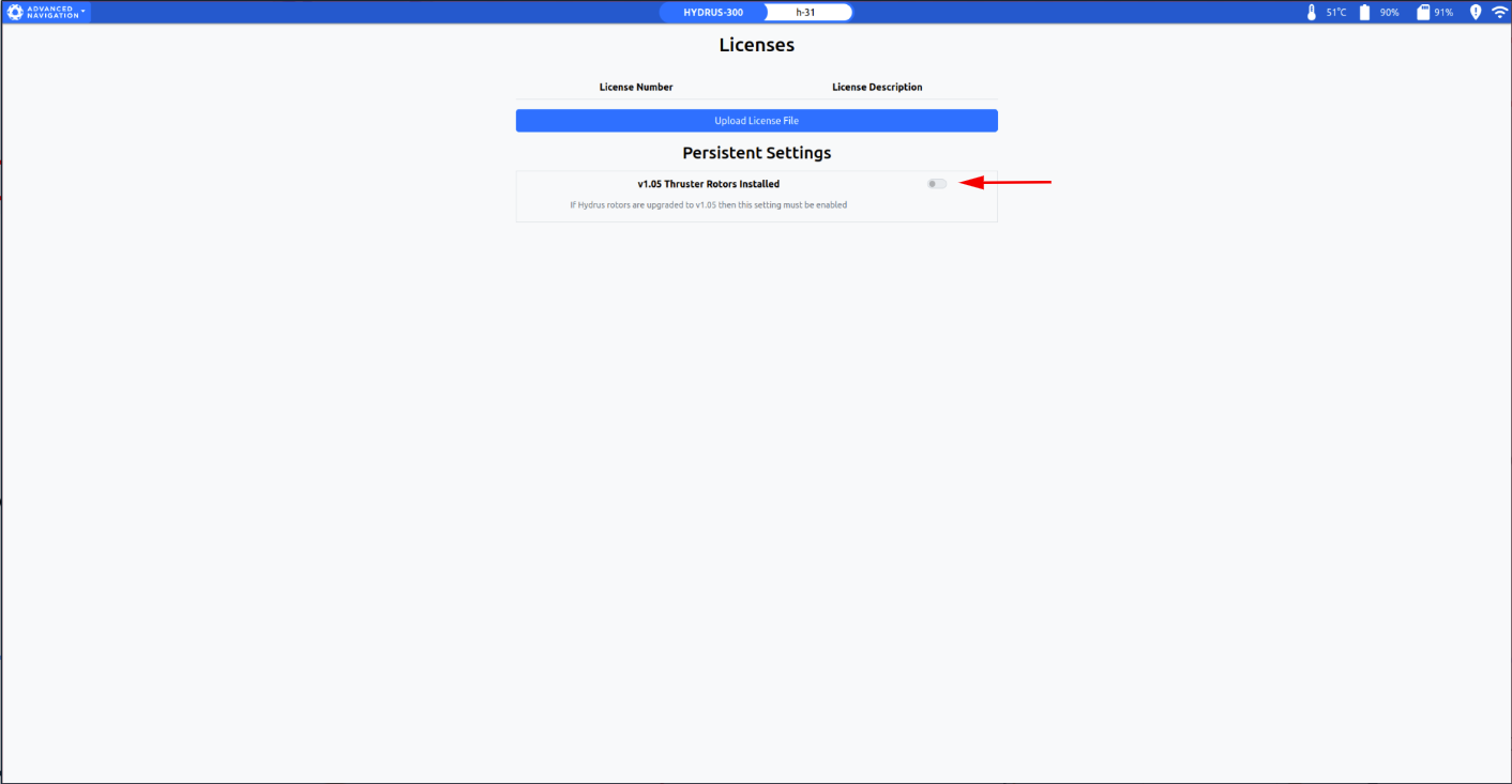
Confirm that all v1.0 rotors have been replaced with HYDRUS-ASSEMBLY-ROTOR-CCW-02 rotors.

Restart the Hydrus unit to apply software support for HYDRUS-ASSEMBLY-ROTOR-CCW-02 rotors.


Note: Once Hydrus has restarted, run a basic testing Hydrus mission in safe conditions to confirm everything was installed correctly.
HYDRUS-ASSEMBLY-ROTOR-CCW-02 rotors are now ready for operational use.