View Menu
From the View menu, you can select pages to view real-time data from the INS.
Map
[INS Manager - Desktop only]
View > Map takes the user back to the home which features the map display.
Device Information
View > Device Information displays the unit's:
- Serial number.
- Device ID.
- Firmware version.
- Hardware version.
This page is useful when requesting technical support.
Subcomponent and GNSS Receiver Information
The INS Manager Web > View > Subcomponent Information and INS Manager Desktop > View > GNSSS Receiver Information displays detailed information about the GNSS receiver fitted to the INS.
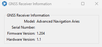
INS Manager Desktop GNSS Receiver Information Dialogue
If your device is fitted with a Trimble GNSS receiver, the Desktop dialogue features a License Update text field. To upgrade your licence, copy and paste the license key into the License Update field and click Send.
Status
View > Status shows the current system status, filter status, and GNSS status flags, as reported by System State Packet (ID#20) and Raw GNSS Packet. (ID#29)
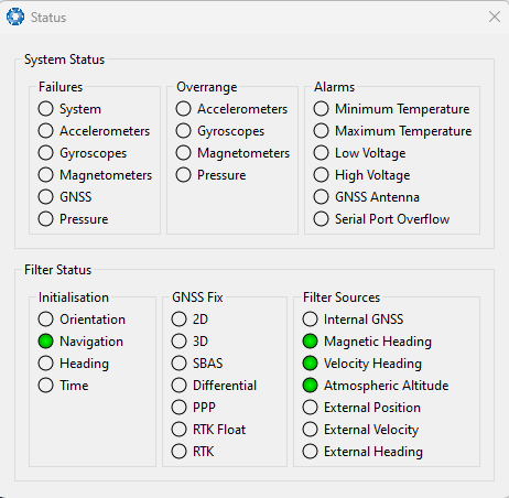
INS Manager Desktop Status Dialogue
Satellites
View > Satellites shows detailed information on the satellites visible to the INS GNSS receiver. The display includes a satellite skyplot, a table, and an SNR (Signal-to-Noise Ratio) graph.
The plot shows the SNR of each satellite or each satellite at the primary and secondary antenna. As a guideline, SNRs should be within 5-10 dB of each other in the absence of cable or antenna faults. Elevation and azimuth are displayed in units of degrees.
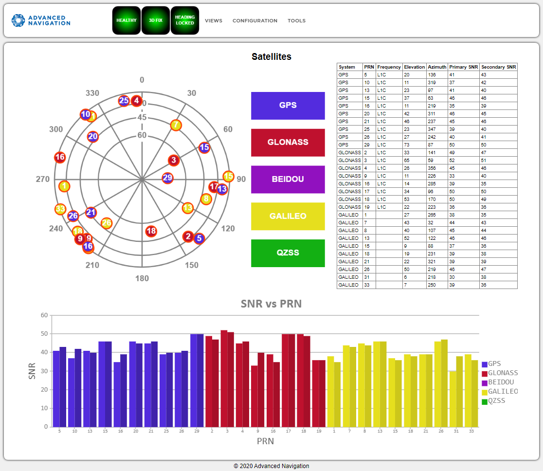
INS Manager Web Satellites Table
Raw Sensors
View > Raw Sensors displays the raw IMU sensor values.
The plots include accelerometer, gyroscope, and magnetometer readings. Temperature readings are provided for a range of sensors, including T(Ax), T(Ay), T(Az) for the accelerometer axes; T(Gx), T(Gy), T(Gz) for the gyroscope axes; T(M) for the magnetometer; and T(P) for the pressure sensor.
The lower plot visualizes air pressure. Internal temperature sensors are also reported but do not reflect the general environmental temperature.
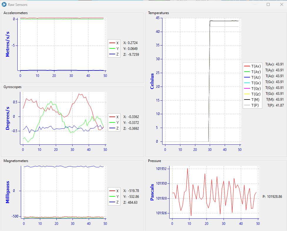
INS Manager Desktop Raw Sensor Outputs
Orientation
View > Orientation shows the INS orientation, angular velocity, and orientation error.
Courseis the path determined by measuring sequential positions.
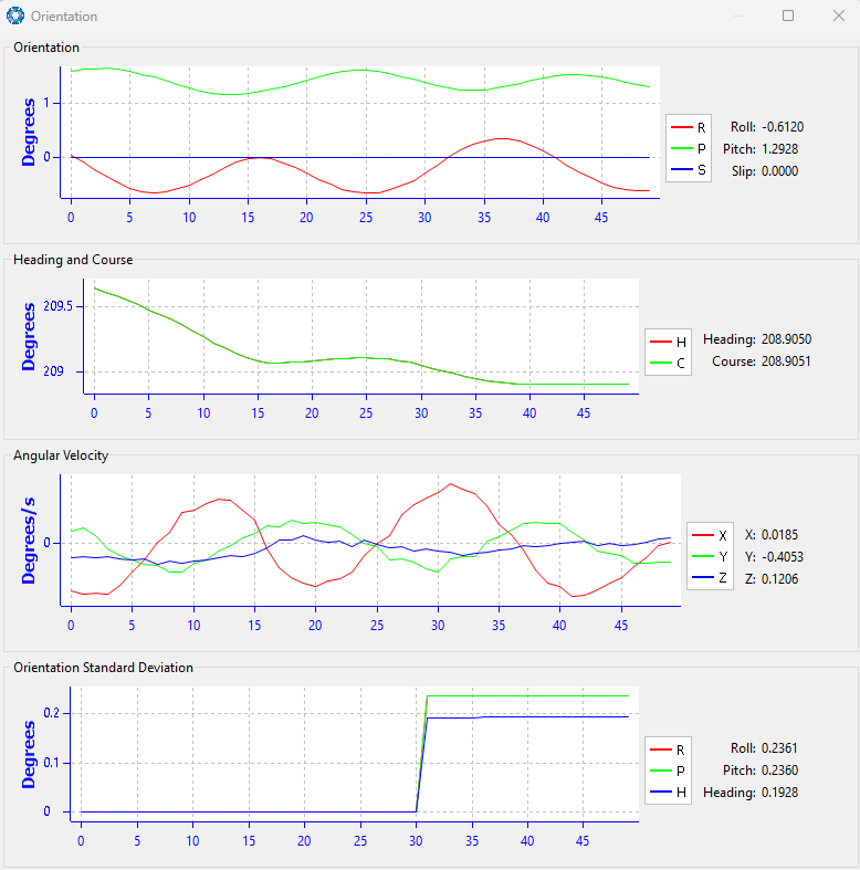
INS Manager Desktop Orientation Outputs
Position
View > Position shows the INS position and position error (standard deviation). Latitude and longitude are converted to North and East metres from a reference point.
The position reference point can be reset in INS Manager - Desktop or by refreshing the web page in your browser with INS Manager - Web.
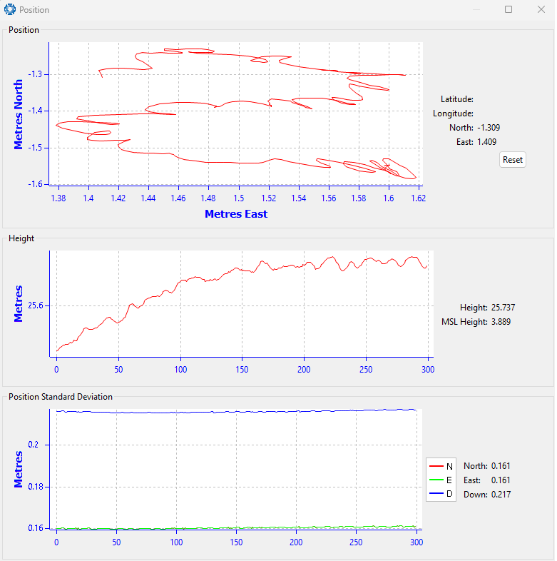
INS Manager Desktop Position Outputs
Velocity and Acceleration
View > Velocity and Acceleration shows the INS velocity, acceleration, and g-force over time.
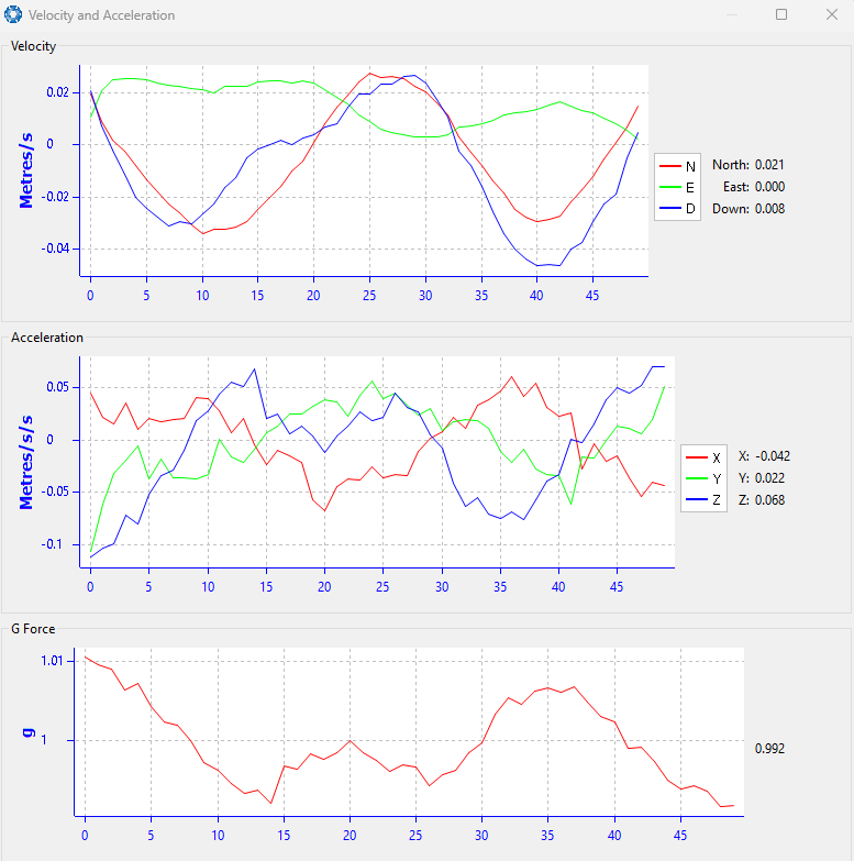
INS Manager Desktop Velocity and Acceleration Outputs
Time
[INS Manager - Desktop only]
View > Time displays the time for the connected device in Unix, UTC, or Local time formats, ensuring accurate timekeeping and synchronisation across systems.
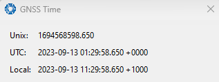
INS Manager Desktop Time Dialogue
Communications
[INS Manager - Desktop only]
View > Communications shows statistics on the data packets received from the INS (e.g., packets decoded, bytes discarded, LRC/CRC errors and is useful for diagnosing any signal quality problems on the connection, such as signal strength or connectivity.
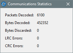
INS Manager Desktop Communications Dialogue
Vessel Motion
View > Vessel Motion This page displays the vessel motion (heave, surge, sway) at up to 4 reference points. For data to display, the Vessel Motion Packet (ID 89) must be configured in the Configuration Menu dialogue. Reference point offsets are configured in the Configuration Menu dialogue.
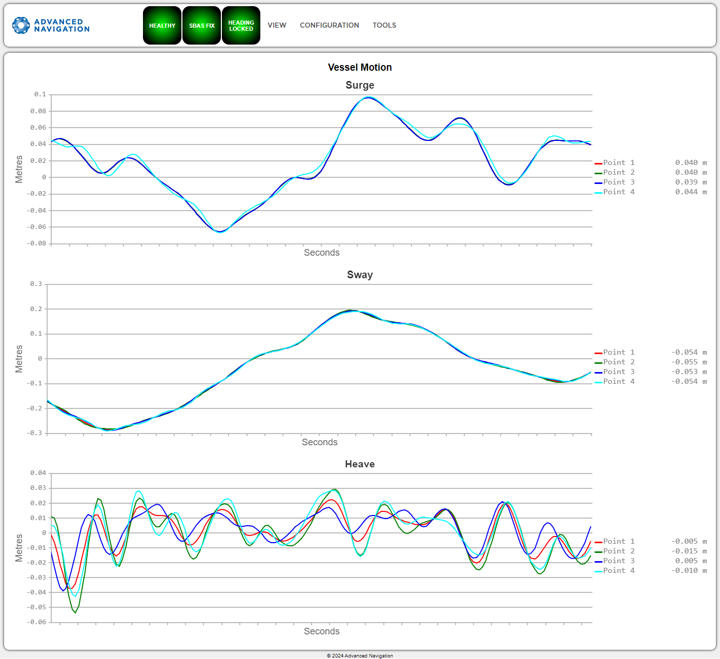
INS Manager Web UI Vessel Motion Page
Heave
View > Heave displays the heave at up to 4 reference points. For data to display, the Heave Packet (ID 58) is configured in the Configuration Menu dialogue. Reference point offsets are configured in the Configuration Menu dialogue.
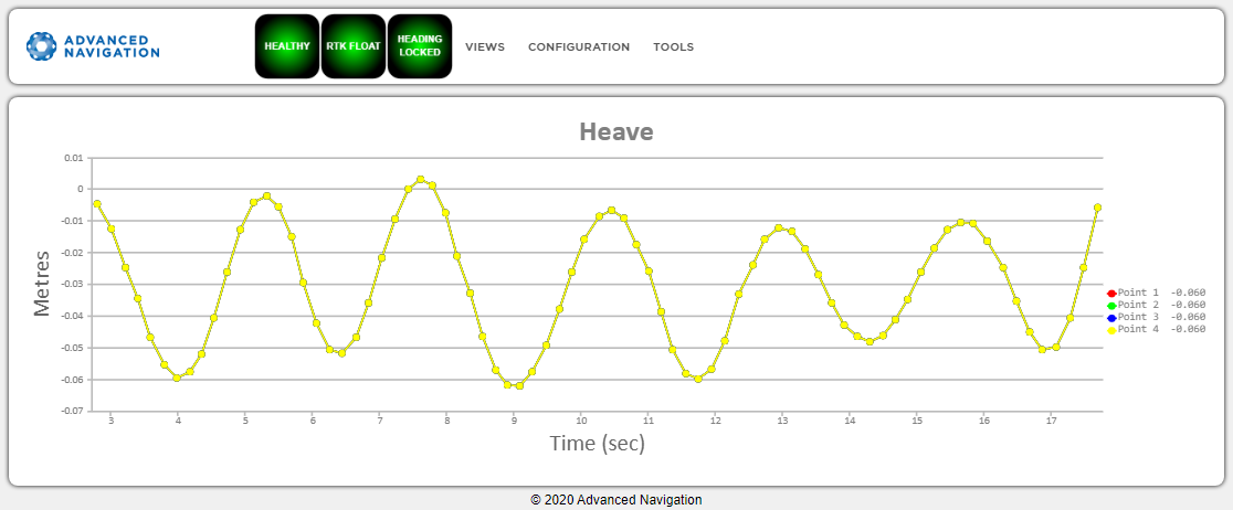
INS Manager Web UI Heave Page
North Seeking Status
View > North Seeking Status displays the current status and initialization messages.
Note: North Seeking Alignment is used to derive the heading based on gyrocompassing, which determines true north from the rotation of the earth. Gyrocompassing is utilised to establish a heading reference when alternative sources, such as dual-antenna GNSS or velocity heading, are unavailable.
| Status Messages | Description |
|---|---|
| Awaiting position via GNSS or manual initialisation | An approximate position is required. Initialisation commences once position is available (via GNSS or the Manual Initialisation page). |
| Initialising, please wait | The process of determining heading has started. |
| Alignment initialised via alternate source | Alignment is bypassed because heading has been successfully established via an alternate source (e.g., dual antenna, velocity, or external input). |
| Heading alignment complete | The system has successfully determined heading. |
Heading Alignment - Status Messages
| Warning Messages | Description |
|---|---|
| Initialisation restarted - excessive motion detected | The initialization has restarted due to excessive motion. |
|
Initialisation restarted - change in latitude detected |
The initialization has restarted due to a significant change in latitude. |
| Initialisation restarted - Change in COG lever arm detected | The initialization has restarted due to a change in the Centre of Gravity (COG) lever arm configuration. |
| Warning - Check latitude, value out of range | A discrepancy between the current latitude and the alignment algorithm was detected. Verify the current latitude is correct. |
Heading Alignment - Warning Messages
External Data
[INS Manager - Web only]
View > External Data acts as a jump page to open time-based data graphs for each supported external source. External sources must be connected and configured appropriately for the corresponding packet to report valid data.
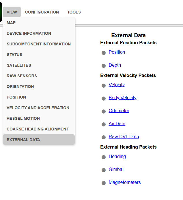
INS Manager Web UI External Data Selection Page
The indicator color next to the External Packet Link reflects the data validity:
| Indicator color | Validity of incoming data |
|---|---|
| Green | Valid |
| Grey | Invalid |
Aiding Source Status
View > Aiding Source Status Shows the status of Aiding Sources, covering:
-
Enabled
-
Online: Receiving data
-
Valid: Data is valid and usable by the filter
-
Origin: (Internal, [Port], Offline)
-
Type: [Format] such as "ANPP"
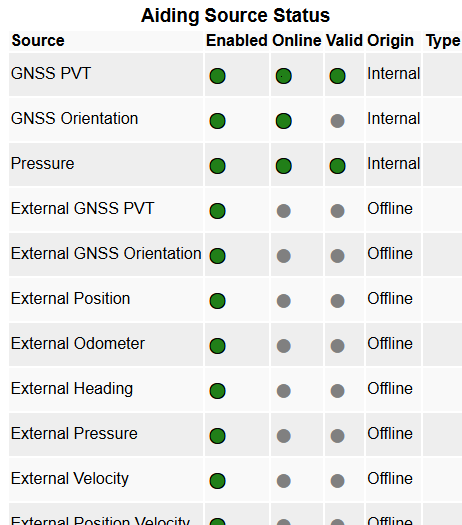
INS Manager Web UI Aiding Source Status