Configuration Menu
The Configuration menu contain options to configure the INS.
Configuration Export
Configuration > Configuration Export is used to export or import all the INS settings to or from a file. This is useful to restore a unit to a preset configuration at a later date or for batch configuration of multiple units.
INS Manager Desktop Configuration Export Dialogue
Filter Options
Configuration > Filter Options are used to enable or disable aiding sources and optimize algorithms bases on known conditions.
For Vehicle Type, select the most appropriate option for your application.
For most applications, filter options can be left as their defaults.
See Filter Initialisation for more information on these specific settings.
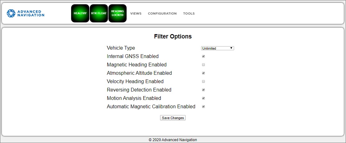
INS Manager Web Filter Options Page
Sensor Ranges
Note: The sensor range page is available for some of the INS products, (including Certus, Certus Mini, GNSS Compass). The sensor range can only be modified for these products; other products offer a fixed sensor range.
Configuration > Sensor Ranges page is used to set the dynamic range of the sensors. If you are experiencing over-range events during operation, these settings should be used to increase the range of the sensor which is reporting the over-range. The lowest ranges give the best performance, so make changes slowly and monitor the results.
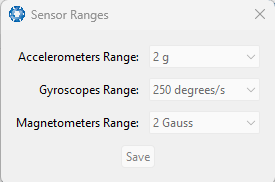
INS Manager Desktop Sensor Ranges Dialogue
Data Ports / Packet Rates
Configuration > Data Ports (Web) Configuration > Packet Rates (Desktop) allows you to specify which data packets or messages are output on a periodic basis and at what rate via serial or Ethernet ports.
The default packets enabled for the primary port are the System State Packet (ID #20) and the Raw Sensors Packet (ID #28) at 20 Hz and these typically provide all the data that a user will require. These two packets need to be enabled for the data graphs to update in the INS Manager. Other ANPP format state packets can be enabled as required.
Note: Packet rate configuration applies only to the data port which the Manager is connected to. To configure other ports, the Manager must be connected to that port.
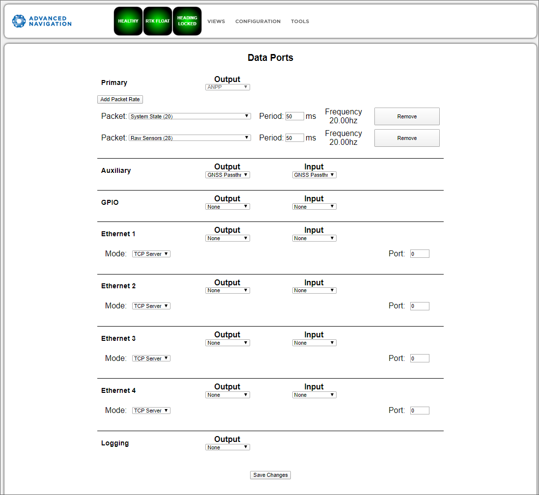
INS Manager Web Data Ports Page
Alignment
Configuration > Alignment is used to set the alignment offsets of the system installation. It is important to set the values correctly to ensure accurate results.
For most applications, only the GNSS antenna offset values need to be entered and the rest of the values can be left at their factory defaults of zero.
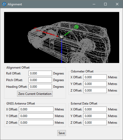
INS Manager Desktop Alignment Dialogue
Alignment Offset
If the INS is installed into the vehicle with the positive X axis pointing forwards and the positive Z axis pointing down, then no alignment offset is required and the roll, pitch and heading offset values can remain at the factory defaults of zero.
If the unit is installed in a different orientation then the roll, pitch and heading offset must be entered. For example, if the unit is installed on its side with the X axis pointing up and the Z axis pointing forwards and no change to the Y axis, then this would result in a pitch offset of +90 degrees with roll and heading remaining zero.
If there is a small misalignment due to mechanical mounting error this can be compensated for by setting the vehicle stationary on a level surface and clicking the Zero Current Orientation button.
Note: Zero Current Orientation will only correct for roll and pitch offsets, the Heading offset must be entered manually and saved after using this function.
GNSS Antenna Offset
The GNSS antenna offset is measured from the centre of the INS unit to the phase centre of the primary antenna in the orientation of the Body Coordinate Frame: (X positive forward, Z positive down).
Odometer Offset
The odometer offset is measured from the centre of the INS unit to the point at which the vehicle's tyre being measured makes contact with the road in the body co-ordinate frame (X positive forward, Z positive down). If your odometer is not measuring a specific wheel, the offset should be to the point on the ground beneath the measurement point. If, for example, your car is a front wheel drive and you are using the velocity from the car OBDII port, the measurement point would be midway between the two front wheels.
External Data Offset
These values are only required for speciality applications operating with an external source of velocity and position data. The offsets are used when providing NMEA Input, External GNSS, or with an Air Data Unit. When using a DVL, use the odometer offset.
Baud Rates/Port Mode and Baud Rates
Configuration > Baud Rates (Web) Configuration > Port Mode and Baud Rates (Desktop) is for setting the baud rates for the GPIO, primary and auxiliary ports.
The factory default baud rate value for these ports is 115200 bps.
Note: Some machines running Microsoft Windows do not support higher baud rates. When changing baud rates, it is recommended to test the baud rate configuration first, without ticking the Permanent box. This way, if it is not possible to communicate at the higher baud rate, a power cycle can be used to revert to the previous baud rate setting.
For newer INS products, the ports can be configured in software to RS232 or RS422. The factory default is dependant on your product.
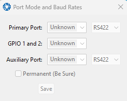
INS Manager Desktop Baud Rates Dialogue
GPIO
Configuration > GPIO allows the user to configure the input and output functions of the GPIO and Auxiliary ports. These functions are described in detail in Dynamic Pin Functions. These functions change dynamically and are effective immediately upon clicking Save Changes.
Note: The GPIO port functions at RS232 levels for data functions and 0 to 5 volt (or 0 to 3.3 V) levels for all other functions. The auxiliary port functions at RS232 or RS422 levels for data functions and 0 to 5 volt (or 0 to 3.3 V) levels for all other functions. The internal hardware automatically reconfigures based upon the selected function.
The default values for these settings are Inactive. The dedicated 1PPS signal is active by default.
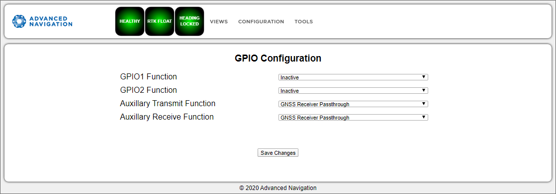
INS Manager Web GPIO Configuration Page
Odometer
Configuration > Odometer allows the user to configure the odometer pulse length and offset. See Odometer and Odometer Pulse Length for more information on the use of odometers. The odometer offset is also applied when using a DVL input.
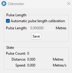
INS Manager Desktop Odometer Dialogue |
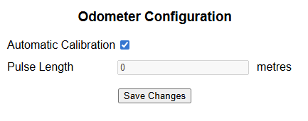
INS Manager Web Odometer Dialogue |
Reset
Configuration > Reset. From this page you can select buttons:
ResetPerform a powers cycle. No configuration settings or state data are lost.Cold StartClears all filters, and connections are reset and must be re-established. No configuration settings are lost.Factory RestoreResets all INS settings back to their factory defaults, including state data and all configuration settings. Re-enable the DHCP Client and loses any static IP address settings. Erases the hot start data so that the system is forced to perform a cold start.
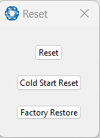
INS Manager Desktop Reset Dialogue
Reference Point Offsets
Configuration > Reference Point Offsets page allows the user to set measurement points away from its default position at the physical centre of the INS unit. The primary reference point offset applies to data from all ANPP packets as well as all peripheral output such as NMEA messages and Heave Point 1. When the values are zero the measurement point is the centre of the INS unit.
The Heave Points 2 to 4 allow the user to offset reference points for the heave values 2 to 4 in the Heave Packet.
The Centre of Gravity (COG) Lever Arm Offset should be used to define where the centre of gravity is for the vehicle. It is useful in applications, such as a surface vessels, to improve the ability of the North Seeking Gyrocompass Heading to complete alignment.
These offsets are applied to the values in the Heave Packet and Vessel Motion Packet.
Note: These values only apply to the Heave Packet and Vessel Motion Packet. NMEA, TSS and Simrad heave is not affected by the values in this dialogue which are always measured at the centre of the INS unit.
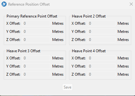
INS Manager Desktop Reference Position Offset Dialogue
GPIO Output
[INS Manager Desktop only]
Configuration > GPIO Output page allows the user to configure the NMEA0183, TSS1 and SIMRAD output rates for the GPIO and Auxiliary port. These output rates will be observed with respect to the actual output selected in the GPIO port configuration.
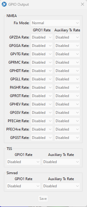
INS Manager Desktop GPIO Output Dialogue
Manual Initialisation
Configuration > Manual Initialisation is used to manually initialise the INS when a GNSS fix is not available. Setting the position will initialise the navigation filter. Setting the heading will also initialise the heading filter.
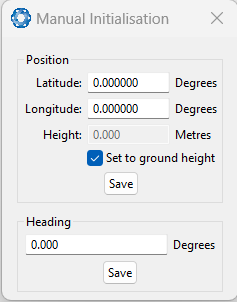
INS Manager Desktop Manual Initialisation Dialogue
Dual Antenna
This Dual Antenna page is to be deprecated.
Parameters should be updated in the page: Configuration > Aiding Sources > Internal GNSS Oritentation.
Configuration > Dual Antenna is used if the primary and secondary GNSS antennas are not installed in their recommended and default positions of primary front and secondary rear, at the same height.
If it is not practical to mount the antennas in the recommended alignment, the alternate alignments must be entered into this page. It is recommended to try and use one of the automatic offsets where possible, where the antennas must be installed in one of four different automatic offset orientations aligned on an axis.
If it is not possible to use one of the automatic offsets, the antennas can be installed in any configuration and a manual offset should be entered. The manual offset is measured from the central base of the secondary antenna to the central base of the primary antenna in the body co-ordinate frame (X+ forward, Z+ down). If using a manual offset, be careful to measure the offset accurately, as even small offset errors can result in relatively large heading errors. For example, 2 cm error = 1.15 degrees heading error with a 1 metre antenna separation.
- When using an automatic offset, the manual offset values are ignored.
- When using a manual offset, the automatic offset selection is ignored.
- When using automatic offset, the manual offset values will show the distance that the INS has automatically measured.
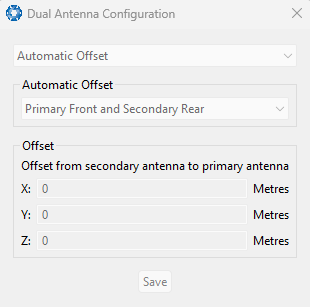
INS Manager Desktop Dual Antenna Dialogue
Gimbal
[INS Manager Desktop only]
Configuration > Gimbal is used in gimbal specific applications.
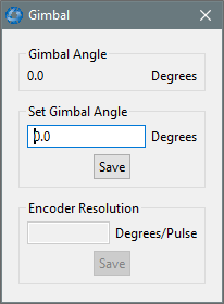
INS Manager Desktop Gimbal Dialogue
Ethernet Settings
Configuration > Ethernet Settings allows you to switch between DHCP and Static IP selection. When the DHCP Client is disabled you need to enter the TCP/IP settings if you wish to access the INS Manager Web interface.
If you are only connecting to the INS via the primary serial port these settings can be ignored.
The default is for the Ethernet mode to be set to DHCP.
Note: Ethernet settings are only available for INS devices with an ethernet interface.
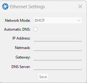
INS Manager Desktop Ethernet Settings Dialogue
NTRIP Client
[INS Manager Web only]
Configuration > NTRIP is used to connect to a network DGPS (Differential GPS, an older standard for GNSS corrections of lower performance than RTK) or RTK service to stream correction data to the INS for DGPS or RTK. The NTRIP client requires the INS has an available internet connection to the NTRIP Caster to function.
The source of the corrections data can be either your own base station, configured as an NTRIP Caster, or a third-party service. Either way, you will need the login details for connecting to and authenticating with the NTRIP Caster, and identifying the nearest mountpoint. For more details on the connection steps, refer to the Manual Initialisation page.
Troubleshooting NTRIP Caster Connections
Some mount points require the INS send its position. To do this, click the Report Position check box, and then click Save Changes. The current INS position will then be sent to the NTRIP Caster every 10 seconds.
If you cannot get the list of mount points, ensure the Host Address and Port number are correct for your NTRIP Caster.
If the Connection Status is not green, and says UNAUTHORISED this indicates an incorrect username or password.
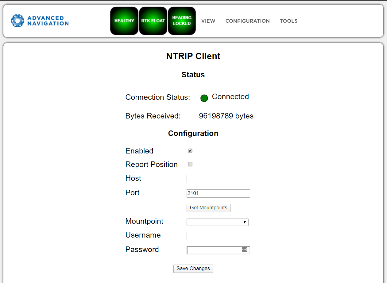
INS Manager Web NTRIP Client Page
CAN Settings
Configuration > CAN Settings allows you to enable or disable the CAN functionality. If you are only connecting to the INS via the primary serial port then these settings can be ignored.
The default for CAN is Enabled at 1,000,000 baud rate. A CANOpen EDS file is bundled with the firmware download or can be downloaded from the Advanced Navigation webpage.
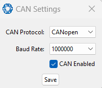
INS Manager Desktop CAN Settings Dialogue
Advanced
[INS Manager Web only]
Configuration > Advanced page allows you to set the voltage level of the GPIO and 1PPS signals lines along with the packet rates.
The options are 5 V, 3.3 V, or Disabled. The default is 5 V.
Note: The dedicated 1PPS signal is active whenever the voltage is set to 5 V or 3.3 V, and is therefore active by default.
The CANopen output packet rates can be configured as the period between packets in milliseconds within the range of 10 ms to 10,000 ms. The default is 50 ms.
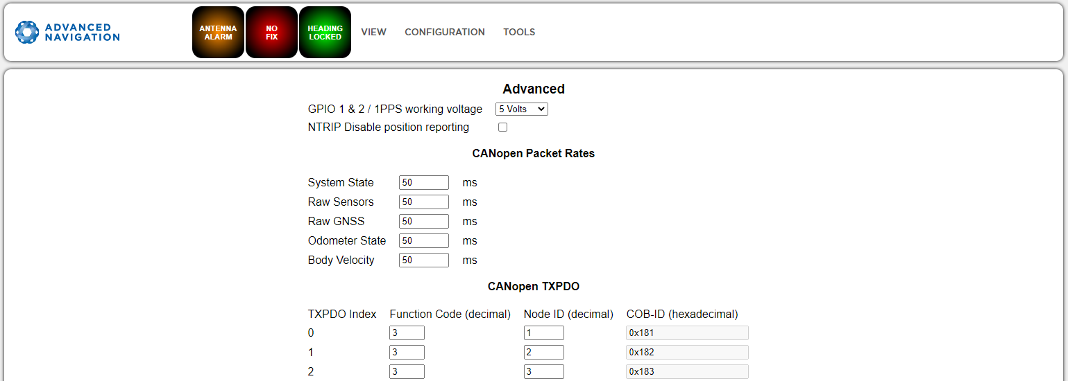
INS Manager Web Advanced Page
GNSS Configuration
Configuration > GNSS Configuration allows you to select constellation configurations based on the type of GNSS receiver installed.
If an invalid configuration is entered, the system will revert to the previous configuration when you try to save the changes. To confirm that changes have been successfully saved, close and re-open the GNSS Configuration page.
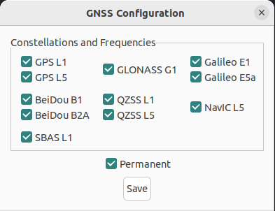
INS Manager Desktop GNSS Configuration Dialogue
U-blox GNSS Receiver Configuration
When using a u-blox GNSS receiver, the following configuration rules are applicable:
- By default, GPS, Galileo and GLONASS are enabled, along with SBAS and QZSS correction services.
- When selecting a GNSS constellation, all frequencies for that constellation must be selected, with the exception of GPS and Beidou.
- GPS and Beidou can be enabled with L1/B1 frequency only, and a second frequency is optional.
- SBAS and QZSS correction services can also be enabled for all constellation configurations, except when using GPS, Galileo and BeiDou together, or when GPS L1 is not enabled.
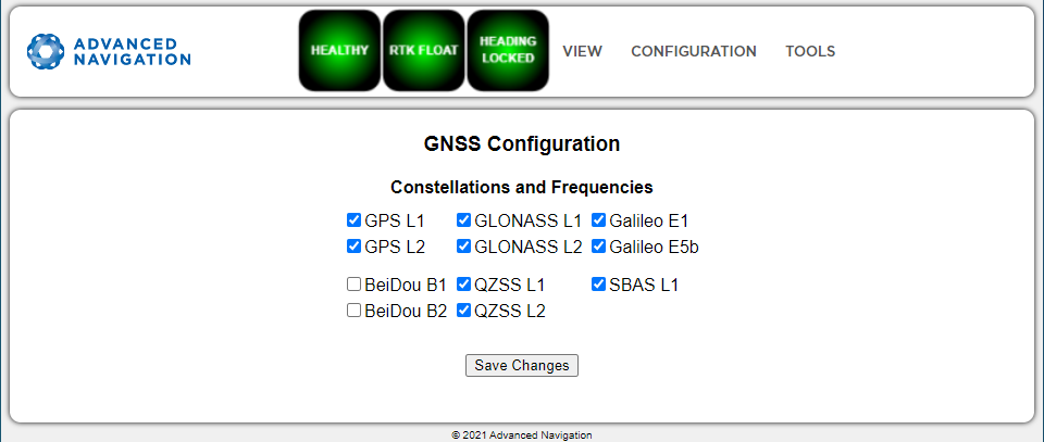
INS Manager Web U-blox GNSS Configuration Page
The table below lists the supported constellations and the corresponding GNSS sample period depending upon the number of constellations selected. When setting the Configuration Menu, the packet rate of the Raw GNSS Packet and Raw Satellite Data Packet are automatically adjusted to the next lower integer multiple of the sample period.
| # of Constellations Configured | Sample Period | Example Effective Packet 60 Rate | Supported Constellation Configurations |
|---|---|---|---|
| 1 | 40 ms | 1 ms - 39 ms = 40 ms (25 Hz) | GPS |
| 50 ms | 1 ms - 99 ms = 50 ms (20 Hz) 100 ms - 149 ms = 100 ms (10 Hz) 150 ms - 199 ms = 150 ms (6.67 Hz) |
Galileo GLONASS BeiDou NVC |
|
| 2 | 67 ms | 1 ms - 133 ms = 67 ms = 15 Hz | GPS & GLONASS |
| 72 ms | 1 ms - 143 ms = 72 ms = 14 Hz | GPS & Galileo | |
| 100 ms | 1 ms - 199 ms = 100 ms (10 Hz) 200 ms - 299 ms = 200 ms (5 Hz) |
GPS & BeiDou All other combinations |
|
| 3 | 125 ms | 1 ms - 249 ms = 125 ms (8 Hz) 250 ms - 374 ms = 250 ms (4 Hz) |
GPS, GLONASS & Galileo GPS, GLONASS & BeiDou (no correction services) All combinations |
| 4 | 143 ms | 1 ms - 285 ms = 143 ms (7 Hz) | GPS, Galileo, GLONASS & BeiDou All combinations |
| 5 | 200 ms | 1 ms - 399 ms = 200 ms (5 Hz) | All combinations |
U-blox Supported GNSS Constellation Configurations
Trimble BD992 GNSS Receiver Configuration
When using a Trimble BD992 GNSS receiver, the following configuration rules are applicable:
- For any given constellation, the first (1) frequency must be enabled in order to receive additional frequencies
- Galileo and BeiDou are licensed separately, see Part Numbers and Ordering page for details.
- L Band corrections are available on this receiver, however require an additional subscription to Omnistar or RTX. Advanced Navigation does not supply these, contact Trimble for further details.
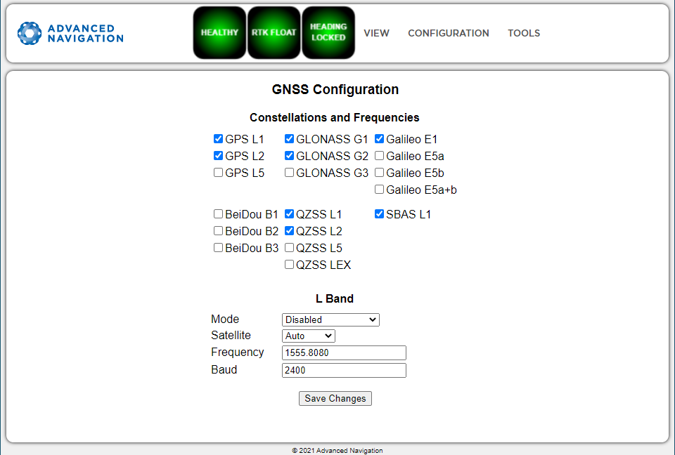
INS Manager Web BD992 GNSS Configuration Page
Aiding Source Configuration
Configuration > Aiding Source allows you to configure aiding sources:
-
Enable: Off/On
-
Position Offset
-
Orientation Offset
Note: The Position Offset refers to the position of the sensor from the INS defined body point (typically the center of the INS), in body coordinates.
Note: For dual antenna GNSS, the GNSS antenna orientation values represent the position of the primary antenna from the secondary antenna, in body coordinates.
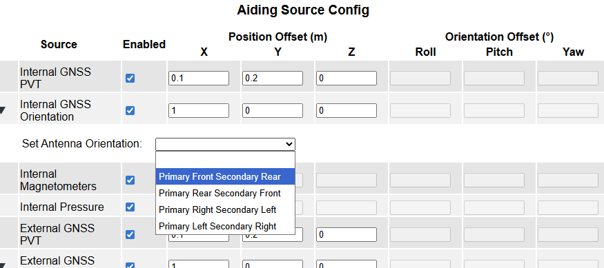
Note: Remember to select Save Changes after entering new parameters.