Chimera Land Reference Manual
Introduction
The Chimera Laser Velocity Sensor (LVS) provides non-contact, highly accurate 3D body velocity updates directly to Advanced Navigation's INS navigation filter, bypassing inaccuracies inherent in mechanical odometry.
Chimera is engineered for extreme environments in defense and mining, specifically targeting operational theaters where GNSS is compromised or denied. It integrates seamlessly into Advanced Navigation's Inertial Navigation System (INS) ecosystem to deliver very accurate, long-duration dead-reckoning navigation in a rugged and small Size, Weight and Power (SWaP).
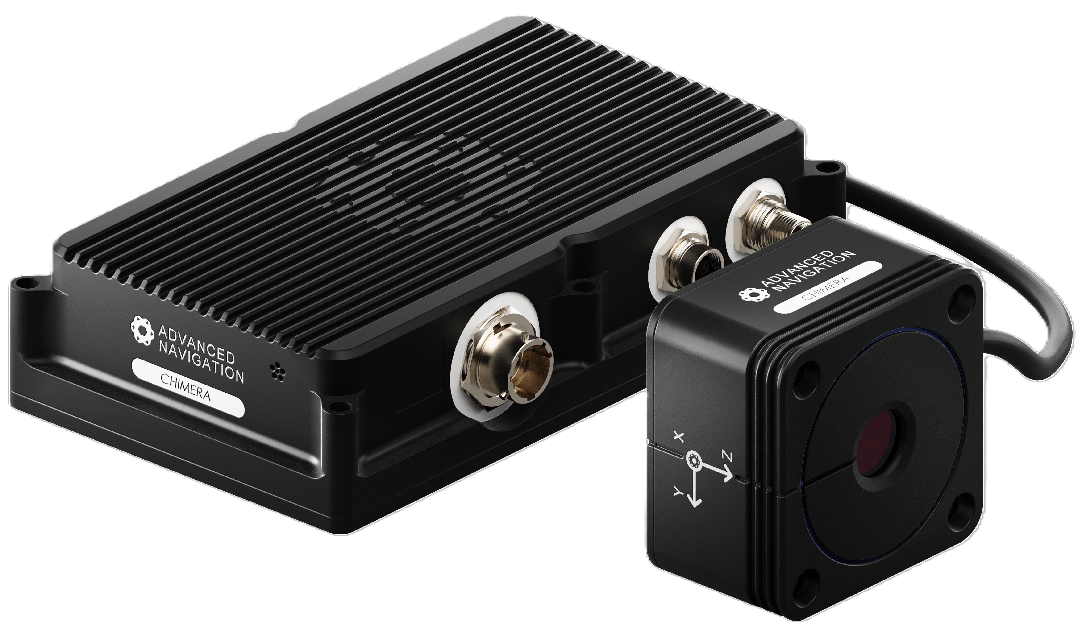
Image: Chimera Laser Velocity Chimera Body and Head
Foundational Knowledge
Before working with an Inertial Navigation System, you should have background knowledge of geospatial concepts, and principles of Inertial Navigation Systems.
Helpful resources include:
Manual Revision History
| Version | Date | Changes |
|---|---|---|
| 1.2 | 2026-10-16 | Added Optical Head reference point diagrams and alignment steps. Explained the Chimera Lever Arm setting. Updated Disclaimer. Added Firmware Release Notes to the manual. Updated to Firmware v1.124, which includes alignment settings not retained on update, ethernet-only INS connection, configuration validation, improved auto alignment, and INS installation offsets. Minor doc updates. |
| 1.1.3 | 2026-05-27 | Minor improvements to explanations |
| 1.1.2 | 2026-04-09 | Fixed typo in part numbers Minor doc updates |
| 1.1 | 2026-02-27 | Minor doc corrections |
| 1.0 | 2026-02-10 | Initial version |
Firmware Changelog
| Version | Date | Changes |
|---|---|---|
| 1.124 | 2026-10-12 |
Existing alignment settings are not retained when updating to this firmware release. Record alignment values before updating, or run Device Alignment afterwards. Details: Chimera Land Firmware Release Notes 1.124 - PDF |
| 1.11 | 2026-04-02 | Fixed UI issue caused when not connected to internet |
| 1.1 | 2026-02-10 | Initial version |
Hardware Changelog
| Version | Date | Changes |
|---|---|---|
| 1.0 | 2026-02-10 | Initial version |
Disclaimer
Advanced Navigation Pty Ltd (ABN 49 156 101 549) and/or third parties hold intellectual property rights in the products (including hardware, firmware, and software, including Software as a Service “SaaS”), technology, names, logos and designs referred to in this document.
No licence, express or implied, by estoppel or otherwise, to any intellectual property rights is granted under this document.
If any part of this document refers to any third party products or services it shall not be deemed a license grant by Advanced Navigation for the use of such third party products or services, or any intellectual property contained therein or considered as a warranty covering the use of such third party products or services.
Copying, reproduction, modification or distribution of this document is permitted only with Advanced Navigation's express written permission, except where the document is expressly identified in writing as being for public release.
The products and documentation are licensed as per our online terms (which are available on our website), and are subject to the applicable Advanced Navigation Licence Terms and/or Additional Licence Terms.
Use of our products constitutes acceptance of those terms.
Our products are provided "as is" as at the time of acquisition.
To the maximum extent permitted by law, Advanced Navigation gives no warranty, express or implied, including as to accuracy, reliability or fitness for a particular purpose, and assumes no liability for its use.
Nothing in this notice excludes any right or remedy conferred by applicable law that cannot lawfully be excluded including any consumer law rights.
Unless expressly represented otherwise and confirmed in writing by an authorised Advanced Navigation representative in a written agreement, the products are not recommended, authorised or warranted for use in military, aircraft, space, life-saving, life-sustaining, or other high-risk or hazardous applications requiring fail-safe or fault-tolerant performance, or in any application where failure may result in personal injury, death, or severe property or environmental damage. Any such use is at the purchaser's own risk.
This product and associated technology may be subject to export control and sanctions laws as per our online terms. Users are responsible for compliance with export control laws.
© 2026 Advanced Navigation Pty Ltd. All rights reserved.
System Specifications
Operating Specifications
| Specification | Chimera Land + Boreas D90 |
|---|---|
| 3D Dead Reckoning Positional Error per traveled
distance Based on distance 1 to 100km, average velocity ≥ 7km/hr |
0.05% TD (CEP50) |
| 3D Body-Velocity Scaling Error | 200 ppm (max) |
| 3D Body-Velocity Axis Stability | 4 mm/s (max) Allan Deviation, τ = 1s |
| Operating height | 0.1 to 3.0m |
| Operating speed | 0.8 to 200 km/h |
| Supported ground surfaces | Bitumen, dirt and gravel roads; concrete, clay, and stone; grassland, sand, rock; and similar solid surfaces. |
| Surfaces with sub-optimal performance | Still water, snow, and ice. |
Hardware Specifications
| Specification | Chimera |
|---|---|
| Input Operating Voltage | 9 to 28 V DC |
| Power Consumption (Typical) | 20 W |
| Operating Temperature (Head and Body) | -10 °C to +65 °C |
| Storage Temperature (Head and Body) | -40 °C to +85 °C |
| Body Dimensions | 212 x 126 x 50 mm |
| Body Weight | 1.35 kg |
| Optical Head Dimensions | 84 x 84 x 51 mm |
| Optical Head Weight | 0.809 kg |
| Laser tilt angles relative to optical head | 15° |
| Mounting tilt range relative to target surface | -30° to 30° |

Image: Optical Head Tilt Angles
Interfaces
| Interface | Data Rate | Connector |
|---|---|---|
| 1 x Ethernet | 10/100/1000 Base-T | M12-X |
| Optical cable to Chimera Head | N/A | Custom MPO |
| Power | N/A | M12A-17 |
| 2 x RS232 | 4,800 to 115,200 baud | M12A-17 |
| 1 x General Purpose Input (1PPS) | 1 Hz | M12A-17 |
| 1 x Laser Enable Input | 0.1 Hz | M12A-17 |
Compliances
| Compliance | Standard | Description |
|---|---|---|
| Ingress Protection (Body) | IEC 60529: IP66 | High-pressure water jet. |
| Ingress Protection (Head) | IEC 60529: IP69K | High-pressure/high-temperature washdown. |
| Sand and Dust | MIL-STD-810H: 510.7 | Blowing dust and sand in arid environments. |
| Operating Temperature | MIL-STD-810H: 501.7 / 502.7 | High/Low Temperature operational stability. |
| Vibration | MIL-STD-810H: 514.8 | Composite Wheeled Vehicle vibration profiles. |
| Operational Shock | MIL-STD-810H: 516.8 | 15 g, 11 ms Terminal-Peak Sawtooth pulse. |
| Crash Hazard Shock | MIL-STD-810H: 516.8 | 50 g structural integrity for safety. |
| Salt Fog | MIL-STD-810H : 509.7 | Corrosive maritime atmospheres. |
| Electrical (EMI/EMC) | MIL-STD-461G | Electromagnetic compatibility and interference. |
| Electrical (Transients) | MIL-STD-1275E | Characteristics of DC electrical systems. |
| Eye Safety - Class 1 | IEC 60825-1 | No protective eyewear required. |
Hardware and Interfaces
Chimera Mechanical Drawings
Chimera Body Drawings
The following diagrams describe the Chimera body.
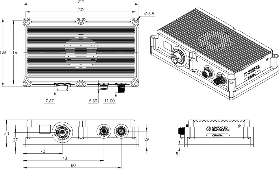
Image: Chimera Body
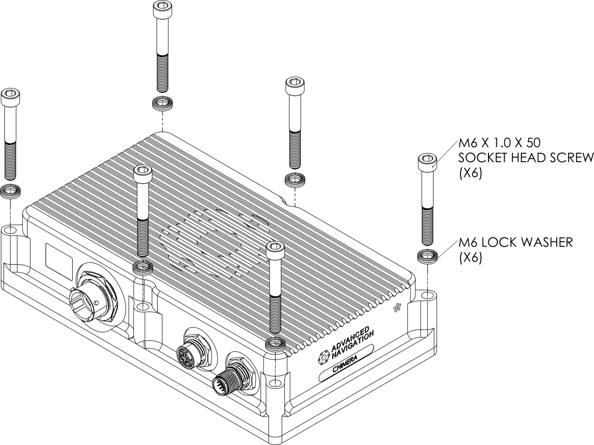
Image Chimera Body with screws
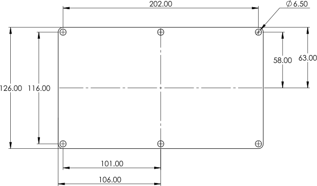
Image: Chimera Body mounting
Chimera Cable Bend Radius
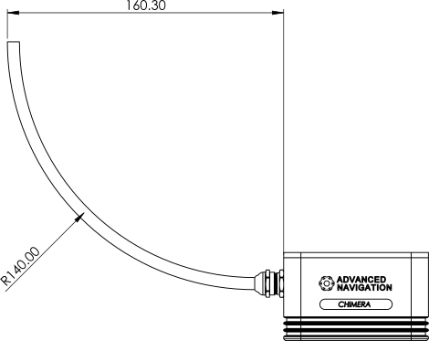
Image: Optical Head Cable Bend Radius
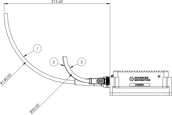
Image: Chimera cable bend radius
| Label | Description | Bend Radius |
|---|---|---|
| 1 | Optical Head cable | 140 |
| 2 | Ethernet cable | 50 |
| 3 | M12 Breakout cable | 50 |
Chimera Optical Head Drawings
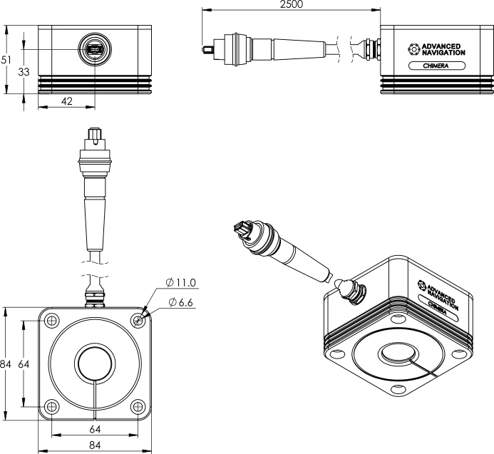
Image: Optical Head Mechanical Drawings
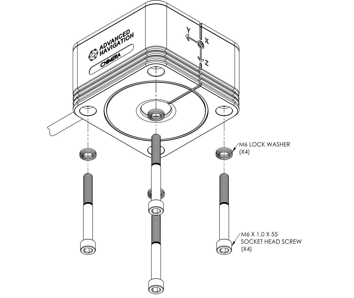
Image: Optical Head with screws
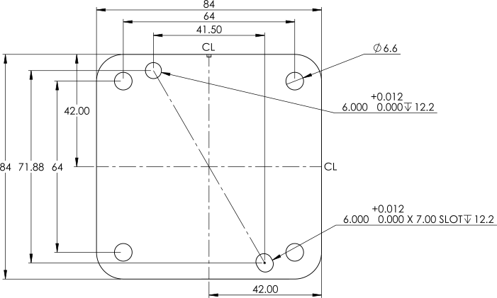
Image: Optical Head mounting
Optical Head Reference Point
The optical head reference point is the physical location used to determine relative position between the optical head and the INS.
It is the theoretical intersection of the four laser beams, below the optical head.
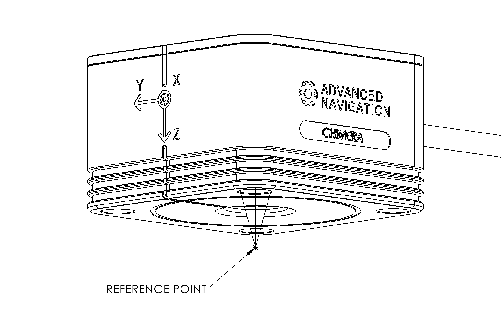
Image: Optical Head Reference Point located at the intersection of laser beams below the optical head.
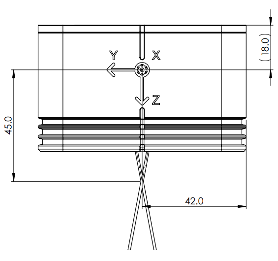
Image: Optical Head Reference Point dimensions.
Chimera Fasteners
The Chimera body and head should be fastened with the following fasteners (or similar).
| Fasten to | Part Description | Quantity | Screw Torque |
|---|---|---|---|
| Chimera Head | M6 X 1.0 X 50 Socket Head Screw | 6 | 8 Nm |
| Chimera Head | M6 Lock Washer | 6 | |
| Optical Body | M6 x 1.0 x 55 Socket Head Screw | 4 | 8 Nm |
| Optical Body | M6 Lock Washer | 4 |
- Alternative screw lengths may be used to fit the mounting location.
- A torque wrench or driver should be used to ensure correct torque.
Laser Enable Switch
The Laser Enable Switch triggers the laser to be turned off or on. It can be replaced by a short if you wish the laser to be permanently on.
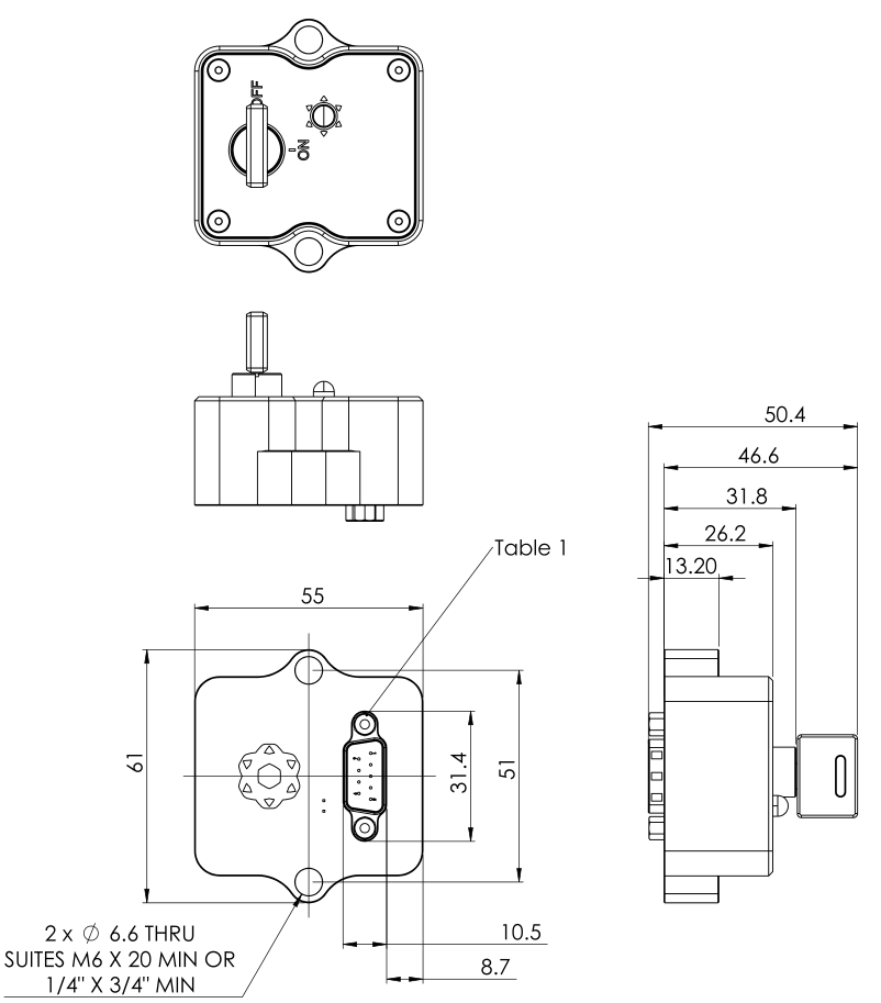
Laser Enable Switch ICD
IO Breakout Cable
The IO Breakout Cable provides multiple connectors to facilitate power and serial communication. The cable connects to the Chimera Body via a 17-pin M12 connector and breaks out into the following functions:
| Breakout Cable | Acronym | Cable Type | Pin | Signal |
|---|---|---|---|---|
| Power | PWR | DC Female 2.1x5.5mm | Tip | Power Supply |
| Ring | Supply Ground | |||
| Primary RS232
Serial interface to INS. |
PRIM | DE9 Female | 2 | TX |
| 3 | RX | |||
| 5 | Signal Ground | |||
| Auxiliary RS232
Unused. |
AUX | DE9 Female | 2 | TX |
| 3 | RX | |||
| 5 | Signal Ground | |||
| GPIO
1PPS input. |
GPIO | DE9 Male | 2 | 1PPS |
| 5 | Signal Ground | |||
| Laser Enable
Turn laser on/off. |
LASER | DE9 Female | 4 | Laser Enable Input |
| 5 | Signal Ground | |||
| 6 | System Power Reference | |||
| Discrete
Discrete signals (Unused). |
DSCR | DE9 Female | 1 | PWR_DWN |
| 2 | 1PPS Out | |||
| 5 | Signal Ground | |||
| 6 | Spare pin |
While the breakout cable provides access to multiple interfaces, a typical permanent installation may only require the Power connection.
Chimera Body Thermal Management
The Chimera Body generates heat during operation. To ensure the unit remains within its operational range, it must include an effective thermal management strategy, which typically includes one of:
- Conduction Cooling: Mounted to a metallic surface, acting as a heat sink. The use of a high-quality thermal interface material (TIM) is recommended to minimize thermal resistance.
- Convection Cooling: Active airflow maintained across the unit’s housing to ensure the internal temperature remains within operational limits.
Operating the Chimera Body without adequate thermal management may result in the unit overheating, resulting in degraded performance or thermal shutdown.
Part Numbers
Chimera Land
The Chimera Land LVS can be purchased:
-
Individually.
-
As an Evaluation Kit, which additionally includes accessories required to setup the unit.
| Part Number | Description |
|---|---|
| CHIMERA-LAND | Chimera LVS land variant, with body and head. |
| CHIMERA-LAND-EK | Evaluation Kit for the Chimera LVS land variant, including including the sensor body, optical head, and cables and accessories for setup. |
Advanced Navigation INS: You will require an Advanced Navigation Inertial Navigation System to communicate with the Chimera LVS. The INS will need to be purchased separately.
What's included
- Don't mix-and-match body and head components:
- Each Chimera Optical Head is factory calibrated with it's paired Chimera Body.
- Using a different Optical Head to its original Body will result in sub-optimal performance.
The following components are included with your purchase.
| Part Number | Description | CHIMERA-LAND | CHIMERA-LAND-EK |
|---|---|---|---|
| AN-ASY-LVS1-SENSOR | Chimera-Land Laser Velocity Sensor - Body | 1 | 1 |
| AN-ASY-LVS1-REMOTE-OPTICAL-HEAD | Chimera-Land Optical Head with attached fiber optic cable and Multi Fiber Push-on (MPO) connector | 1 | 1 |
| AN-CABLE-M12-POWER-COMMS-2M | M12 Breakout Cable to:
|
1 | |
| AN-CABLE-M12-ETHERNET | Ethernet Cable M12 X-Code Male Plug to RJ45 Plug Cat6a Cable Assembly, TPE Jacket 3M | 1 | |
|
AN-ASY-CHIMERA-LASER_SWITCH |
Switch to turn on/off the laser. | 1 | |
| COTS-LVS-MPO-FIBRE-CLEANER | Optical Fiber Connector Cleaner | 1 | |
| COTS-LVS-IR-CARD | Infrared Sensitive Card Facilitates seeing IR beams |
1 | |
| SUPPLY-24V | 24V, 36 Watt, DC Power Supply, with Universal Input
Wallmount Multi-Plug (US,EU,UK,AU) DoE/CEC Level VI Connects to barrel jack |
1 |
Optional Accessories
The following Chimera accessories may be required for specific use cases.
| Part Number | Description |
|---|---|
| COTS-AMPH-PTMPO | Bulkhead adapter. Facilitates the passage of laser light outside of a flame-proof enclosure while keeping all electronic components contained inside. Only necessary if the user's setup necessitates the use of a flame-proof box to house the electronics. |
| COTS-AMPH-MPO-EXTENSION | MPO Cable Extension Connects from the Chimera body to the bulkhead adapter on the flameproof box. It allows the remote head to connect to the outside of the bulkhead adapter on a flame proof box. |
User Supplied Components
The following commonly sourced components will typically be used during a bench test, evaluation and implementation.
| Description | Quantity |
|---|---|
| Ethernet Switch, DHCP enabled | 1 |
| M5 x 1.0 x 50 Socket Head Screws (or different
length) For Chimera Body |
6 |
| M5 x 1.0 x 55 Socket Head Screws (or different
length) For Optical Head |
4 |
| M6 Lock Washers | 10 |
| Chimera Head Baseplate to connect to the platform. (Optional) | 1 |
| Chimera Body Baseplate to connect to the platform. (Optional) | 1 |