Configuration Menu
These menus contain the set of configuration settings for the INS.
Sensor Ranges
Note: The sensor range page is available for some of the INS products, (including Certus, Certus Mini, GNSS Compass).
The Sensor Ranges page is used to set the dynamic range of the sensors. If you are experiencing over-range events during operation, these settings should used to increase the range of the sensor which is reporting the over-range. The lowest ranges give the best performance, so make changes slowly and monitor the results.
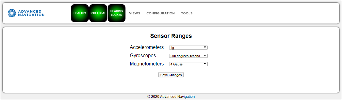
INS Web UI Sensor Ranges Page
Filter Options
Ensure that the Vehicle Type filter option is selected for all applications. For most standard applications, the other filter options can be left as their defaults.
See Filter Initialisation for more information on these specific settings.
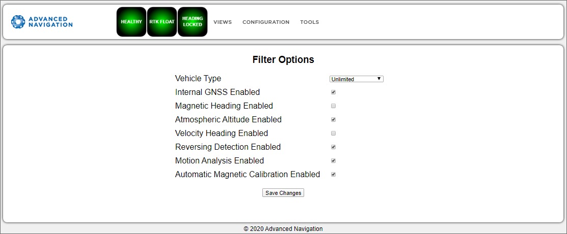
INS Web UI Filter Options Page
Data Ports
The Data Ports page allows you to specify which data packets or messages are output on a periodic basis and at what rate via a range of serial and Ethernet ports.
Note: The GPIOs and auxiliary port are configured in the Data Ports page only if they are being used as serial transmit and receive lines. To configure GPIOs as digital or frequency inputs or outputs, use the GPIO page.
Other data formats available include NMEA0183, GNSS, TSS1, SIMRAD and other formats. For more information see Ethernet Functions
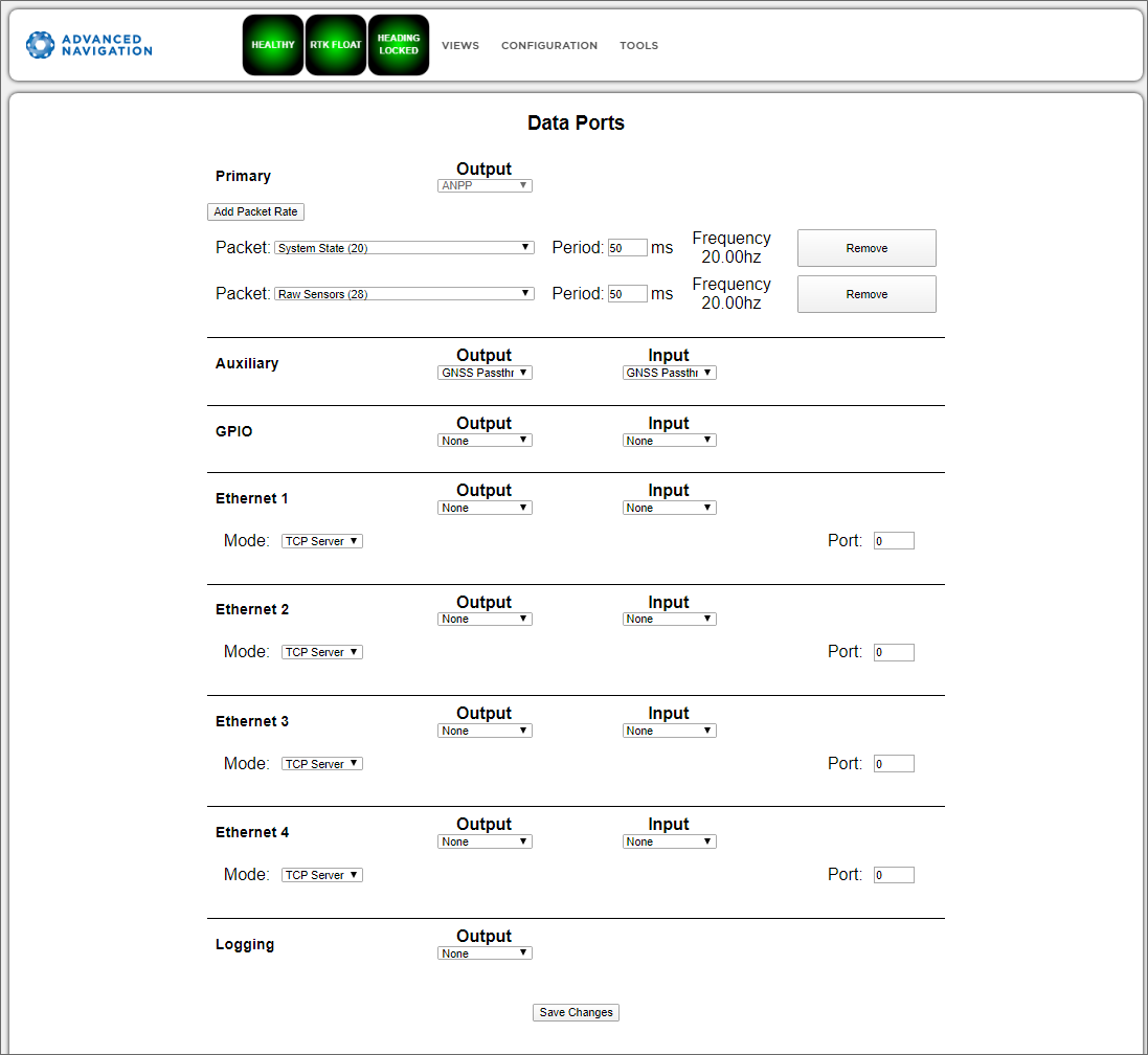
INS Web UI Data Ports Page
Alignment
The Alignment page is used to set the alignment offsets of the system installation. It is important to set the values on this page correctly to avoid degrading performance.
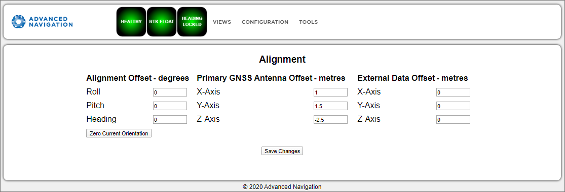
INS Web UI Alignment Page
Alignment Offset
If the INS is installed into the vehicle with the positive X axis pointing forwards and the positive Z axis pointing down, then no alignment offset is required and the roll, pitch and heading offset values can remain at the factory defaults of zero.
If the unit is installed in a different orientation then the roll, pitch and heading offset must be entered. For example, if the unit is installed on its side with the X axis pointing up and the Z axis pointing forwards and no change to the Y axis, then this would result in a pitch offset of +90 degrees with roll and heading remaining zero.
If there is a small misalignment due to mechanical mounting error this can be compensated for by setting the vehicle stationary on a level surface and clicking the Zero Current Orientation button.
Note: Zero Current Orientation will only correct for roll and pitch offsets, the Heading offset must be entered manually and saved after using this function.
External Data Offset
These values are only required for speciality applications operating with an external source of velocity and position data. The offsets are used when providing NMEA Input, External GNSS, or with an Air Data Unit. When using a DVL, use the odometer offset.
Baud Rates
This page is for setting the baud rates for the
For Rugged units, the primary and auxiliary ports can be set to RS232 or RS422. The factory default is RS232 for both ports.
For OEM units, primary and auxiliary ports on the INS A70 are UART only, and cannot be changed to RS232 or RS422. An appropriate adapter/interface is required to connect to a computer.
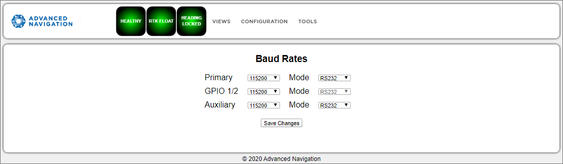
INS Web UI Baud Rates Page
GPIO
This page allows the user to select the input and output functions of the GPIO and Auxiliary ports. These functions are described in detail in Dynamic Pin Functions. These functions change dynamically and are effective immediately upon clicking Save Changes.
Note: The GPIO port functions at RS232 levels for data functions and 0 to 5 volt (or 0 to 3.3 V) levels for all other functions. The auxiliary port functions at RS232 or RS422 levels for rugged units, and TTL levels for OEM units, for data functions and 0 to 5 volt (or 0 to 3.3 V) levels for all other functions. The internal hardware automatically reconfigures based upon the selected function.
The default values for these settings are Inactive. The dedicated 1PPS signal is active by default.
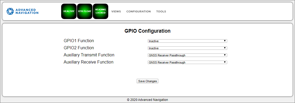
INS Web UI GPIO Configuration Page
Odometer
The Odometer page allows the user to configure the odometer pulse length and offset. See Odometer and Odometer Pulse Length for more information on the use of odometers. The odometer offset is also applied when using a DVL input.
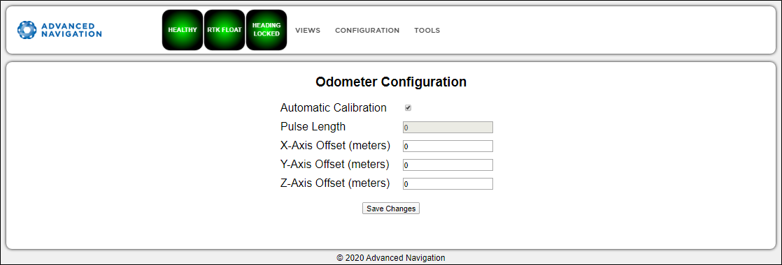
INS Web UI Odometer Configuration Page
Reset
The Reset button causes the system to perform a power cycle. No configuration settings or state data are lost.
The Cold Start button clears all filters, and connections are reset and must re-established. No configuration settings are lost.
The Factory Reset button resets all INS settings back to their factory defaults, including state data and all configuration settings. It also erases the hot start data so that the system is forced to perform a cold start.
Note: A Factory Reset will re-enable the DHCP Client and lose any static IP address settings.
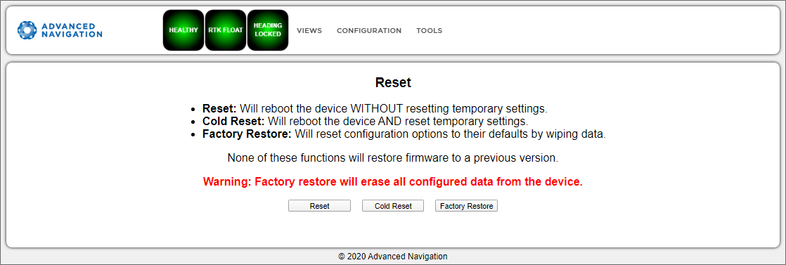
INS Web UI Reset Page
Manual Initialisation
This page can be used to manually initialise the INS when a GNSS fix is not available. Setting the position will initialise the navigation filter. Setting the heading will also initialise the heading filter.
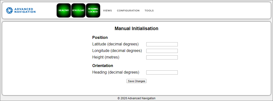
INS Web UI Manual Initialisation Page
Ethernet Settings
The Ethernet Settings page allows you to enable or disable the DHCP Client. When the DHCP Client is disabled you need to enter the TCP/IP settings if you wish to access the web UI.
If you are only connecting to the INS via the primary port these settings can be ignored.
The default is for the Ethernet mode to be set to DHCP.
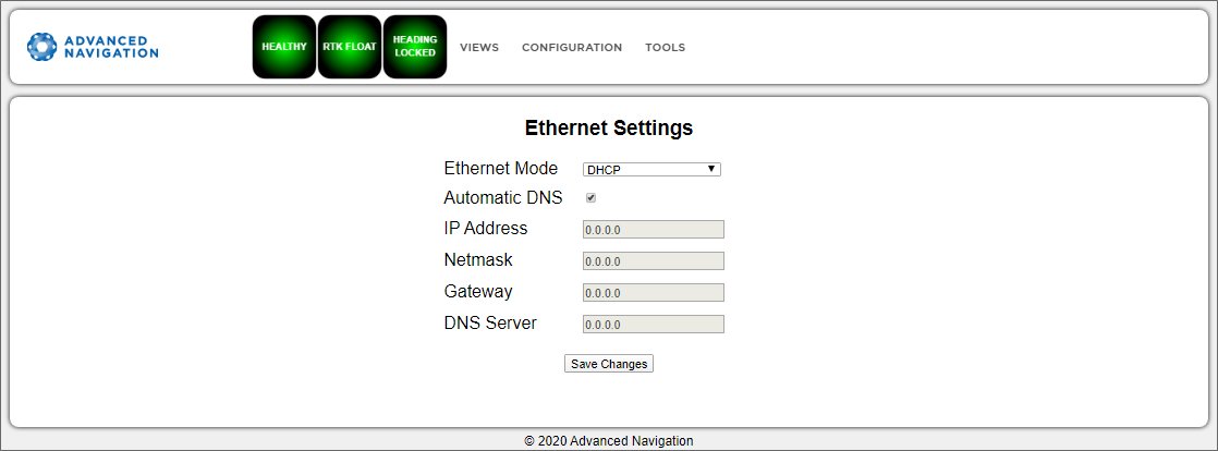
INS Web UI Ethernet Settings page
NTRIP Client
The NTRIP client built into the INS can be used to connect to a network DGPS (Differential GPS, a older standard for GNSS corrections of lower performance than RTK) or RTK service to stream correction data to the INS for DGPS or RTK. The NTRIP client requires the INS has an available internet connection to the NTRIP Caster to function.
The source of the corrections data can be either your own base station, configured as an NTRIP Caster, or a third-party service. Either way, you will need the login details for connecting to and authenticating with the NTRIP Caster, and identifying the nearest mountpoint.
These steps are required:
- Select Enabled.
- For Host/Server, enter the NTRIP Caster address.
- For Port, enter the NTRIP Caster port numbe. This is usually 2101.
- Click Save.
- Click Get Mountpoints.
- Select your mountpoint from the Mountpoint drop down list, being mindful that the distance should not exceed 50km.
- Enter your username in the Username box.
- Enter your password in the Password box.
- Click Save.
To disconnect from the NTRIP Caster unselect Enabled and click Save.
Troubleshooting NTRIP Caster Connections
If you cannot get the list of mountpoints, ensure the Host Address and Port number are correct for your NTRIP Caster.
If the Connection Status is not green, and says UNAUTHORISED this indicates an incorrect username or password.
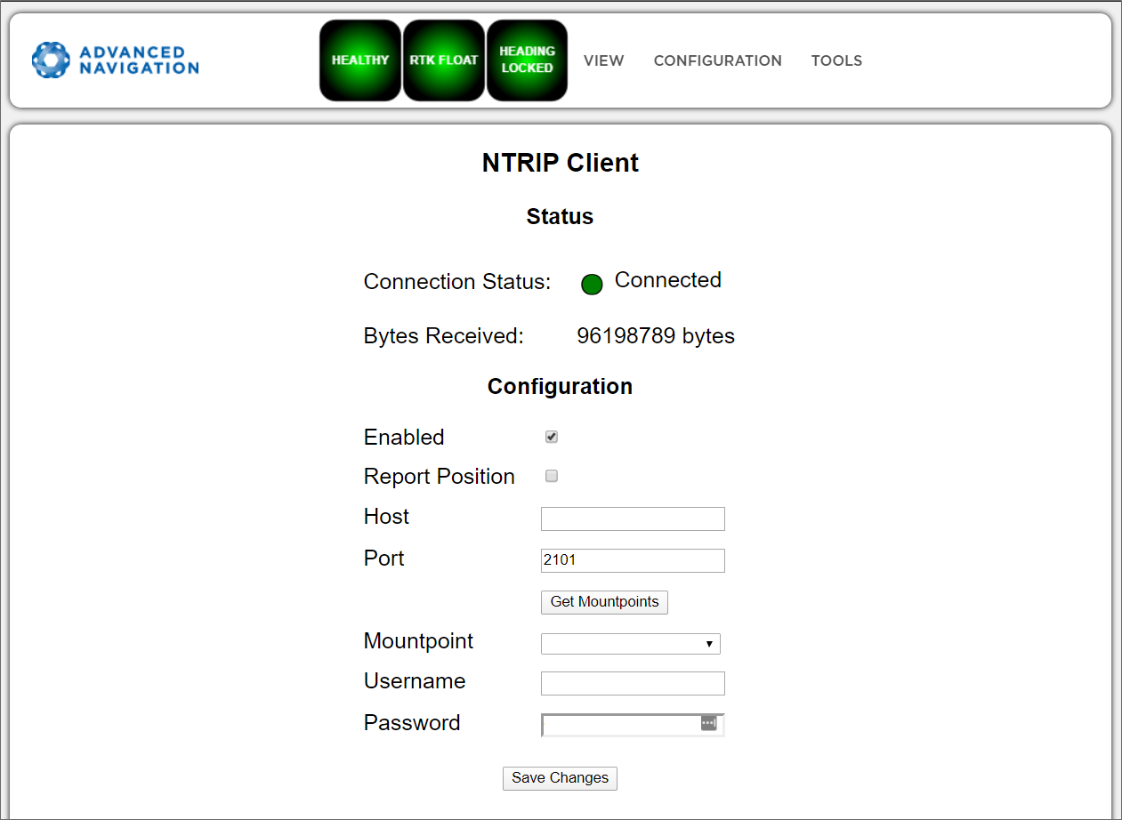
INS Web UI NTRIP Client Page
CAN Settings
The CAN Settings page allows you to enable or disable the CAN functionality. If you are only connecting to the INS via the primary port then these settings can be ignored.
The default for CAN is Enabled at 1,000,000 baud rate. A CANOpen EDS file is bundled with the firmware download.
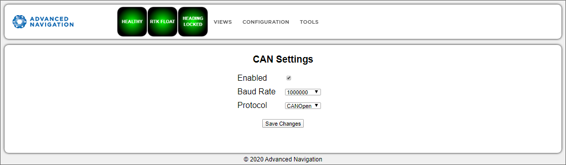
INS Web UI CAN Settings Page
Advanced
The Advanced page allows you to set the voltage level of the GPIO and 1PPS signals lines along with the packet rates.
The options are 5 V, 3.3 V, or Disabled. The default is 5 V.
Note: The dedicated 1PPS signal is active whenever the voltage is set to 5 V or 3.3 V, and is therefore active by default.
The CANopen output packet rates can be configured as the period between packets in milliseconds within the range of 10 ms to 10,000 ms. The default is 50 ms.
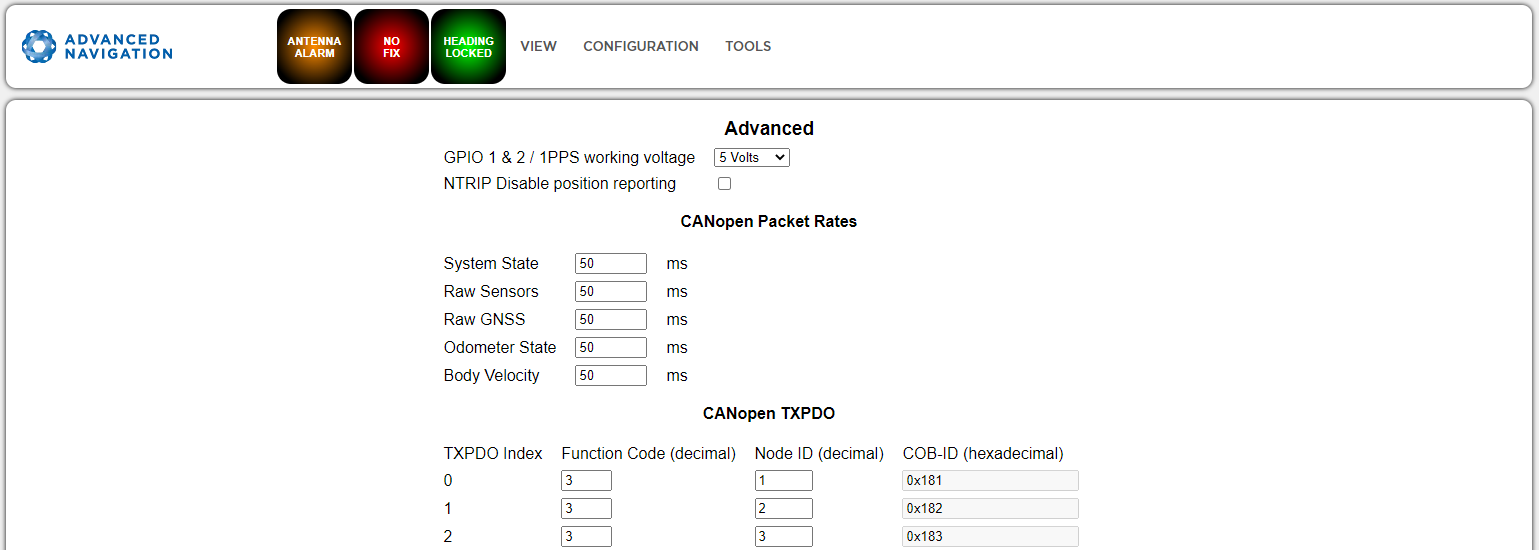
INS Web UI Advanced Page